Last time, I got all my wiring runs in place to illuminate this model. Now it’s time to add some lights, starting with the engine bells.
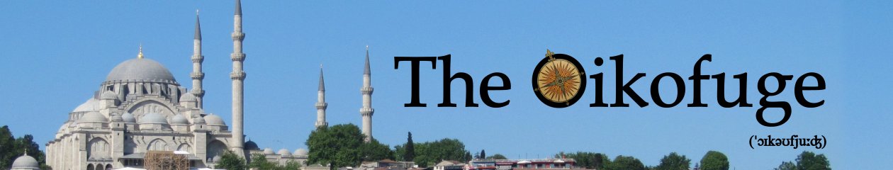
There’s room for a couple of large LEDs inside the flare of the engine bells, which means I can get a light behind both engine nozzles on each of the three engine bells. Here’s one LED in one half of an engine bell, showing how I plan to position my lights:
Click to enlarge
With that decided, I wired up and tested my three pairs of lights:
Click to enlarge
Then there was a decision to make about what to do with the engine nozzles. The kit parts are solid, with a moulded grill. Yay! Monsters make a replacement part moulded of translucent plastic, so there’s the option to paint everything on these parts except where I want light to leak through, between the grill bars. But the Paragrafix photoetch parts I’ll be using for the cockpit interior include a set of nice engine grills, too—so I could drill out the kit parts and insert the metal replacement grills. Here are all the relevant parts, next to the Paragrafix photoetch—Yay! Monsters nozzles at left, kit part at right, engine bell below.
Click to enlarge
My concern with the Yay! Monsters part was that the back isn’t finished. Here’s a comparison with the kit part (on left):
Click to enlarge
You can see that the Yay! Monsters part would need a lot of work to get it to locate properly within the hexagonal engine bell. I also wasn’t sure how neat a final effect I could produce, applying paint on to the translucent grill. So I drilled out the nozzles and used the Paragrafix grills:
Click to enlarge
There’s quite a lot of light inside the engine bells, and I didn’t want it to leak out anywhere except through the grills. So I lined the bells with metal foil on top of a layer of flat black paint, and then painted the exterior black, too, before finally placing the external layer of kit parts that add detail all around the bell.
Click to enlarge
When I checked for light leaks in a darkened room, I picked up a couple of seams that needed just a little filler and more paint, and one bright spot in the middle of an exterior part, where its locating tab had pushed through the interior foil and was acting as a light duct—a little more foil cured that.
But the hexagons containing the paired engine nozzles presented a problem, with the potential for unsightly light leaks around their edges. The position of the nozzles, very close to the edge of the part, meant that it was going to be difficult to fill any leaks around those edges. After a bit of contemplation, I came up with a solution that involved the diffuser I was going to place inside the grills. I wanted the nozzles to look uniformly dark when not illuminated—no glimpses of the interior foil and LEDs. And I wanted a diffuse illuminant when my engine lights were switched on. Eventually I settled on using a piece of the plastic packaging my LEDs had been delivered in. Here’s a demo—dark side of the plastic at left; plastic stretched and glued over the back of the engine hexagon at centre; final product at right:
Click to enlarge
I dealt with the filler problem by “pre-filling” the edges of the hexagon—leaving a little edge of my plastic diffuser all around the part, and anointing it with fine filler before gluing it into the engine bell:
Click to enlarge
This auto-filled the gap around the edges as I pushed it into place, and the small amount of excess that squeezed out was easily removed with the edge of a damp tissue. Then it was just a matter of checking the final effect:
Click to enlarge
And the dark-room test:
Click to enlarge
Now it was time to add some detail paint to the engine compartment and nozzles. My idea is to produce a quite strongly variegated effect, which I’ll eventually moderate with a uniform blending coat across the whole model.
The idea here is to layer on several shades of grey, with the paint mask orientation shifted and rotated between layers, to produce an overall mottle suggesting fine detail.
For the smoothly panelled front end of the compartment, I started with a dark shade, masked a few panels, added a paler shade, and so on. Here’s the final result:
Click to enlarge
I painted the engines bells mid-grey and then brought up detail with a dark wash:
Click to enlarge
At present the engine bells are just tacked in place with some clear glue. There’s a slight problem with the bells, which is that in the “real” thing, the three hexagons containing the engine nozzles align edge to edge. But the kit parts want to sit very slightly apart. The solution is either to slip in a little sliver of plastic to fill the gap, or to tilt the outer engines very slightly to bring the hexagons together, and I wanted to take a look at my options at this stage.
Here are the hexagons aligned edge to edge:
Click to enlarge
And, actually, the slight tilt turns out to be no big deal, discernible only if you press the hexagons against something flat. So that’s what I’ll go with when I assemble this section permanently.
I was also able to check my wiring runs and light up the engines:
Click to enlarge
Click to enlarge
So that’s all good. Next time, I’ll move to the other end of the kit and start wiring up and illuminating the Paragrafix photoetch cockpit.
This is the large styrene model of the iconic Discovery spacecraft from the film 2001: A Space Odyssey. And when I say large, I mean large—assembled, it’s going to be 42 inches long, which will necessitate the hanging of a whole new shelf chez Oikofuge. To get a sense of its weird proportions, take a look at the “real” thing in profile, in a still from the film:
To keep the kit rigid, Moebius have provided it with a steel spine, which runs from the centre engine bell at rear to the back of the command sphere at front. It consists of two hollow steel tubes, connected by a steel sleeve concealed inside the antenna module, halfway along the length of the spacecraft. That narrow tube running the whole length of the model is going to be important for what I’m planning for this kit, because I want to add some aftermarket detail (cockpit and pod bay) to the front of the model, and also want to add (quite a lot of) lighting.
So I need a place to put the batteries. The command sphere is going to be pretty full of aftermarket detail and wires by the time I’ve finished with it, but the rear propulsion unit contains a lot of empty space. Here it is, partly assembled, showing the run of the rear steel rod.
Click to enlarge
To turn this into a battery compartment I need a removable lid, so I modified the upper kit part so that I can pop it on and off.
Click to enlarge
I’ve extended the locating holes in the concealed side and rear flanges into slots, so that my lid can slide in and out, and I’ve removed a front flange which would otherwise foul the tapered front section of the propulsion unit. Here’s the assembled unit:
Click to enlarge
Before going any further with modifications, I needed to convince myself I actually could run a pair of wires along the hollow steel spine of the kit, from back to front. And, with a bit of effort and some mineral oil, I managed to screw a twisted pair all the way through both metal tubes. Here they are with a battery pack and test light connected:
Click to enlarge
And here are the steel tubes assembled end-to-end, demonstrating the length of the kit:
Click to enlarge
With that option confirmed, I next planned to reduce the length of the rear steel tube so that it terminated inside my battery bay, rather than traversing it. It would, however, need some sort of support structure within the bay, to replace its original anchorage at the back. Here’s my solution to that problem, knocked together from brass rod and styrene. It’s being held in place by the steel tube while the glue dries.
Click to enlarge
Then I needed to measure off how much tubing to remove. I dry assembled the rear engine bell on to the steel tube, and marked off the length at the rear of my support structure:
Click to enlarge
On the principle of measuring twice and cutting once, I also assembled the central cores of the four rear cargo pods, and threaded them on to the rear steel tube, ensuring that enough tube protruded to engage with the central sleeve. Then I pulled my wires back far enough to be out of harm’s way, and Dremelled 1¾ inches off my steel tube. Here’s the post-trimming tubing in position, showing that it both engages with the steel sleeve at the front, and allows my wires to enter the battery bay at rear:
Click to enlarge
There’s room inside for two AA 3V switched boxes, one to supply light to the engines, and one for the command sphere. In due course I’ll glue down a couple of electrical connector blocks in the rear space.
Click to enlarge
To get power into the command sphere itself requires only one hole to be drilled, in the kit part that forms the rear of the sphere. I made the hole just large enough to admit the wires, while still leaving enough plastic to form a stop for the steel tube.
Click to enlarge
At the rear, the original hole for the steel tube gives access to the central engine bell. For the two side units, I drilled holes through the original supporting stubs.
Click to enlarge
And in each engine bell, a few seconds with a rat-tail file was required to create a hole that would allow wires to run all the way to the back of the structure.
Click to enlarge
So far so good. Next time, I’ll start installing lights, and do a bit of painting.
At the end of my previous post, I’d finally managed to assemble the complicated crew gondola of my aircraft. After that, I finished off masking its many, many windows, and then set about airbrushing the underside in RLM 65 pale blue enamel, and the topside in a splinter pattern of RLM 70/71 greens, all from Sovereign Hobbies.
Click to enlarge
Click to enlarge
Click to enlarge
All surfaces were sealed with a layer of Plastikote gloss, ready for the kit’s relatively small supply of decals.
Click to enlarge
Click to enlarge
Then I belatedly turned my attention to the propeller and engine. The Bv 141B’s 14-cylinder BMW 801A engine proved to be its downfall, because these engines were scarce and going to other aircraft The kit’s representation of the engine is half-hearted—just the front seven cylinders, and those undersized. But the engine will be largely concealed by the fan mounted behind the propeller (which, mercifully, the kit has rotating in the correct direction, unlike its rendering of the propeller, which I had to replace).
Click to enlarge
The fan of exhaust stubs, to be mounted behind the engine cowling, provides sixteen rather randomly positioned exhausts. It’s difficult to be sure from photographs of the real thing, but I believe I count twelve outlets, arrayed in a 2:1:3 pattern on each side, with the 3-cluster set a little higher on the starboard side.
Click to enlarge
Here’s the kit part, before and after corrective surgery:
Click to enlarge
After a little painting of the engine parts, it was time to glue all the big bits together and strip off the canopy masks, producing something that (almost) looked like an aeroplane. Here’s the result after a little weathering (dry-brushed silver enamel, LifeColor Liquid Pigment, and some Tamiya powders) sealed with Plastikote matt:
Click to enlarge
Click to enlarge
Click to enlarge
Only a little tidying up was required when I popped off the hatches and upper turret:
Click to enlarge
(There’s a little flake of paint sitting on the main spar in the photograph above, but I fished it out with a cocktail stick.)
The way the kit parts are configured forces the upper gun to point directly backwards, but that would foul the open hatch, so I did a little surgery and swung the gun around to a half-left position:
Click to enlarge
I added the Eduard photoetch gun mount to the underside of the turret, with a little bit of styrene strip added to provide the mounting cross-bar, and then slid the final assembly over the gun barrel and into position. Then I sealed the hole in the dome with a little blob of Kristal Klear:
Click to enlarge
Click to enlarge
Which I then painted red-brown to emulate the leather weather-seal around the real thing:
Click to enlarge
Click to enlarge
The undercarriage went on:
Click to enlarge
Click to enlarge
Then I flipped it the right way up to add a final few details, including my little punch-out panel frame, and the open hatches:
Click to enlarge
Finally, I applied a bit more weathering with Tamiya powders. These aircraft seem to have faded and chipped fairly readily:
Click to enlarge
But I wanted to emulate the more subtle pattern of fading visible in some photographs:
Both the kit and the metal parts show the brake lines running tightly over the compressed oleos, which would be a bit of a disaster when the undercarriage was unweighted. So I carved off the sections crossing the oleos and used some stretched sprue to add a loop of flexible slack instead:
Click to enlarge
From my reference diagram, it seems there was a length of flexible brake line running down the inside of the wheel cover, which I made a mental note to add once I got to the stage of adding the gear covers.
Before I got to that stage, however, I had a bit of a puzzle to solve. Reference photographs of these aircraft usually show that each wheel cover was painted with a section of the large Balkan cross that marked the underside of each wing. For this aircraft, I have one photograph that seems to show this marking, and one that doesn’t:
Click to enlarge
After a bit of deliberation, I decided to add it, despite the fact the kit doesn’t provide the necessary decal, just the two crosses with circular holes for the wheel wells:
So in my ancient graphics program, I used each cross as a mask for its opposite number, like this:
And ended up with the pattern for a couple of decals I could print on white Experts-Choice decal film:
I found that I couldn’t reproduce the appearance of the real aircraft using Eduard’s photoetch gear covers unless I slightly trimmed the lower cover for the oleo scissor links. Here’s the final result, with the decals in place and a little light weathering applied:
Click to enlarge
I also started detailing up the bomb racks, using Eduard’s parts:
Click to enlarge
But I belatedly realized that the appearance isn’t a good match for the real thing:
I was going to have to snip off and rotate the eight little brackets moulded into the kit parts into the “stowed” position of the empty rack; and then I was going to need to reverse the orientation of the kit parts, front for back, to produce the correct final appearance. Sigh.
I attended to some other details at this point. The rear gun was mounted in a swivelling frame in the real aircraft, like this:
Eduard provide photoetch gunsights for the rear and upper gun, but they’re in a single, short part, like the sight on the upper gun pictured here:
So I’ll use the Eduard part as provided for the upper gun, but did some surgery on it to reproduce the photographic appearance of the lower gun:
Click to enlarge
Another small detail I wanted to add was the frame of a punch-out panel in front of the pilot, which you can see in this photograph:
Click to enlarge
I was a little puzzled as to how I might reproduce the smooth shape of the original, but eventually came up with this:
Click to enlarge
I’ve knotted and glued a length of fine wire around a couple of pieces of styrene rod of appropriate diameters. Here’s the result, held in its approximate final position on the canopy frame:
Click to enlarge
The upper and lower wing halves were such a snug fit, I decided I’d paint them separately before assembly, thus avoiding one stage of masking. At this stage I also dealt with a moulded bulge on the underside of the crew compartment, which represents the aircraft’s Direction Finding gear—actually a clear dome lined with metal strips, but I contented myself with painting it gloss black and adding narrow strips of Bare-Metal Foil:
Click to enlarge
I started masking the exterior of the crew gondola, with the upper hatches held temporarily in place with Micro Kristal Klear, but I didn’t mask much of the upper transparency at this point, because I wanted to be able to see what was going on inside as I settled it into place:
Click to enlarge
The underside transparency got a coat of light grey undercoat, to prevent the interior paint from darkening the pale blue underside.
You may also be able to pick out a small hole drilled in the underside canopy frame. This is my revised approach to the vexatious pilot’s gunsight mentioned in the previous post—a vertical rod that runs from the floor between the pilot’s feet to the roof over his head. Eduard provide a photoetch part for this, but it wasn’t clear to me how I was going to ensure it was correctly positioned after I’d closed the top and bottom halves of the canopy. So I’ve now come up with a revised plan, involving a length of fine wire running through holes in the upper and lower canopy, which can be snugged into place and fixed with CA glue after the canopy is closed. A few blobs of CA provide an imperfect appearance of the short crossbars in the real thing, but I figured it would look good enough when seen vaguely through the closed canopy:
Click to enlarge
With the lower canopy in position, I dropped the detailed crew compartment into place:
Click to enlarge
Click to enlarge
Then I threaded through my gunsight wire, and closed the upper canopy:
Click to enlarge
There’s a little bit of filling and tidying to do at the wing root, you’ll see, but otherwise it came together nicely.
This is the classic asymmetrical aircraft designed by Richard Vogt for the Blohm & Voss company. It was intended for short-range reconnaissance and ground support. Eight version “A” aircraft were built, followed by a run of the “B” version, probably around twenty in number, though records are hazy and the final disposition of many aircraft unknown. Production was cancelled before it entered active service—not because it was particularly unairworthy, but because of competition for the scarce BMW 801A engine. It ultimately lost out to the twin-engined Fw 189.
The kit provides parts for the “B” version, and decals and painting instructions for two airframes—call-sign NC+RA (pictured on the box art above) which was one of the test aircraft for the “B” series; and GK+GH, a wrecked late model photographed by Allied troops at Blohm & Voss’s Wenzendorf factory. I’m building NC+RA, using the kit decals but ignoring the painting instructions. Hobby Boss call for a dark grey interior, which would be odd for a Luftwaffe aircraft that first flew in the middle of 1941, so I’ve opted for RLM 02 Grau (a sort of greeny-grey shade), which would be typical for this period of the war. The dark grey RLM 66 Schwarzgrau corresponding to the Hobby Boss instructions wasn’t generally introduced until November 1941. The instructions also call for an upper splinter camouflage pattern of RLM 02 and RLM 71 Dunkelgrün, which would show a fairly high contrast between the pale and dark colours. But I don’t see that in the black-and-white photographs of the real aircraft, on which the upper camouflage colours are almost indistinguishable. So I’m going with the more standard mix of RLM 70/71, which are a dark green and an even darker green.
There’s one big problem with the kit, which is that its propeller is mirror-reversed—that is, it’s designed to rotate in the wrong direction. That’s a fairly significant error in any aircraft model, but for one that is grossly asymmetrical in order to counteract the torque from the engine and propeller, it’s a disaster. Fortunately, True Details make a replacement propeller, which is an essential after-market replacement for this kit. Here’s the True Details prop (left) compared to the kit prop.
Click to enlarge
Although Hobby Boss provide a good level of detail, I’m also using Eduard’s photoetch detail set, which has unfortunately been discontinued since I obtained mine. Another prerequisite for this kit, if you want to retain your sanity, is a paint-mask set for that huge glasshouse of a crew compartment. Montex produce a set of masks for the interior and exterior. Eduard make a set of exterior masks. I hate working with Montex masks, which I find too thick and intolerant of repositioning, but I really wanted to paint this canopy inside and out, so I ended up springing for both Montex (as the only interior option) and Eduard (as my preferred option, for the exterior).
Here are the transparent crew-compartment parts with their Montex masks in position:
Click to enlarge
I partially assembled some of the interior parts, including a fair number of Eduard’s PE details, before applying primer:
Click to enlarge
Eduard provides a bomb-sight which attaches to the right side of the central tunnel at the front of the aircraft (covering one of the paired cannons), but there’s no way in which it can placed so that it’s actually centred on one of the floor windows, so I had to carve it up a little.
After priming, I blocked out some initial colours, and added some more of Eduard’s details:
Click to enlarge
Although Eduard provides a lot of nice instrument panelling, for some reason they omit detail for the unit in the mid-compartment, for which I used the kit’s decal.
The three objects at right, above, are dispensers for the drum-magazines used by the aircraft’s rear and upper MG-51 machine guns. The kit parts depict a stack of five magazines that go all the way to the floor, but the real thing had a gap at the bottom, with the lowest magazine dispensing above this.
I’ve contented myself with blanking out the lowest moulded magazine in the kit part. (Eduard provides some nice PE dispensers, which have a more realistic wall thickness, but the kit parts would need to have their moulded walls carved off and replaced.)
The Eduard set includes a pilot’s harness and two lap-belts, but the instructions only mention the lap-belt for the rear gunner. The crew positions for take-off looked like this:
Click to enlarge
The observer, in the mid-compartment, sat on a little wheeled chair that ran on rails between the upper gun position, above the main spar, and the forward bomb-aiming station. So I added Eduard’s second set of lap belts to the observer’s seat. The kit provides no seating location for the rear gunner, and Eduard’s instructions just have the belts attached to a corner of the floor. But the pilot and observer sat on their parachutes in bucket seats, and I presume the gunner did the same. I built a little seat for him so that he could perch on his parachute, as in the diagram above. It’s all a bit cramped, however. Beside the gunner’s take-off station, there was a box for spent cartridges positioned against the back of the main spar (they tumbled down a canvas tube connected to the upper machine gun). The kit places this in the mid-line, whereas in fact it should be off to one side. Here’s a photograph of the real layout, looking back from the rear gun mount, with the cartridge box at the left of the picture, and the gunner’s station at right.
Click to enlarge
Moving the kit’s cartridge box would also require moving one of the magazine dispensers, which is positioned too far back, which in turn would require surgery to the floor … Sigh. Having already partially assembled and primed the parts, I contented myself with squeezing in a slightly undersized gunner’s seat fashioned from styrene strip.
Click to enlarge
Click to enlarge
I painted up the canopy interior, and removed the masks:
Click to enlarge
The three roof hatches will eventually be modelled open, but I’ll fix them in the closed position with clear glue when I come to paint the external surfaces, and then pop them off later.
Lots of detail needs to go into the interior, including an overhead panel, various instruments, and a gunsight:
Click to enlarge
The object sticking out of the floor transparency at right is a primitive bomb-sight for the pilot, presumably only used if the observer was manning the upper gun position. It’s no more than a vertical rod, coming up from between the pilot’s feet and attaching to the cockpit ceiling. You can get a nice view of it in the Alamy photograph here. Eduard provide a nice PE part, but the problem is how to position this thing properly, since it attaches to the upper and lower canopy parts, which must be close around it. My present solution is to glue the sight in position on the floor, and to attach a thread of monofilament (visible in the photo) to its upper end, which I can then pull through a tiny hole drilled in the roof of the upper canopy as I close the two parts together. I’m slightly nervous that I’ll only succeed in pulling the lower end of the sight off the floor, however, at a mission-critical stage in the assembly process.
The final stage before closing the canopy around the crew compartment was to give the whole thing a bit of weathering—I dry-brushed with flat aluminium and buff enamel, applied a wash of Payne Grey watercolour, and then assembled all the bits and pieces. Here’s the result, just before I added the side walls on the starboard side:
Click to enlarge
Click to enlarge
Click to enlarge
Click to enlarge
Next time: closing the canopy and doing something with all the other bits of the aircraft!
A shorter version of this post was published on 11 October 2017.
There are some things I hate about “in-flight” models of piston-engine aircraft. One is when the aircraft appear to be flying without a pilot; the other is a stationary propeller.
Modellers have a couple of ways of dealing with this second problem. One is to simply remove the propeller blades, leaving only the filled and smoothed spinner visible—it’s a well-recognized technique which many feel produces the most realistic appearance. But it always makes me think, Where’s the propeller? I find the complete absence of anything in the space where the propeller should be is a little distracting. I’m also not very keen on the photo-etched “prop-blur” option, which aims to produce a blurred sector for each prop blade, reproducing what we see in photos and movies, but not what we see with the naked eye.
So what I want to see is a transparent disc of the correct propeller colour(s), with the colour density at each radius matching the relative amount of prop blade and empty space at that radius. Like this:
Click to enlarge
Years ago, I posted a short tutorial about this on WW2Aircraft.net; and shortly after I started this blog, I put up a slightly revised version. But it was light on detail—so now this is the extensively revised, expanded and updated version.
I appreciate that some people can’t be bothered doing all the measuring and editing I’ll describe below, which is intended to produce a prop disc that matches the specific measurements of the propeller. If you’re such a person, I encourage you to skip past the measurement and mathematics and read the start of the section about creating a GIMP gradient. Once you’ve seen how I create a gradient of the correct colour, skip ahead to the section on using that gradient to draw the prop disc, and follow on from there. (To skip the first dose of maths, follow this link.)
The first thing I do is to measure the radius of my kit propeller, and then divide it into eight equal sections, from boss to tip, marking off the divisions with a felt-tip pen. Here, I’m marking up two different kinds of propeller for a Blohm & Voss 138 seaplane:
Click to enlarge
Then I measure the propeller blade width at each of my marked locations. To calculate what proportion of the prop disc is occupied by prop blades at each of my eight points along the radius of the propeller, I first work out the radius at each marked distance, which is just the radius of the propeller multiplied by the number of eighths—the first mark on my 24mm propeller is at 3mm, the next at 6mm, and so on. Then I multiply each of those distances by 2π to derive the local circumference. To find out how much of that circumference is occupied by propeller blades, I take the measured width of a propeller blade at that distance, and multiply by the number of blades. Dividing this length by the total circumference tells me what proportion of the prop disc is occupied by propeller blades.
I use a little Excel spreadsheet to do the calculations for me:
The first column is the number of eighths, measured from the hub of the propeller. The second column converts this to a radial distance. In the third column I’ve entered my measured blade widths, and the fourth column does the maths—multiplying the local blade width by the number of blades, and dividing by 2π times the local radius. You’ll see these numbers turn out to be relatively small, and I find that discs printed with opacities to match are fairly unimpressive, visually—primarily because you can see through even a “zero transparency” layer of ink. So in the fifth column I take the highest number in the fourth column, and express all my numbers as a proportion of that. These are the numbers I’m going to feed to my printer, with 100% representing maximum opacity printing, and 0% full transparency.
I also need to specify a colour for my prop disc. The BV 138 aircraft I’m modelling would have had propellers painted in Luftwaffe Schwarzgrün, which was coded RLM70. I can use the handy digital colour charts created by William Marshall, available here, to discover that RLM70 translates into RGB values of 56/62/50.
So now I’m ready to create my prop disc in a graphics program. I’m going to use GIMP, which has all the tools I need. You can download it here, for Linux, Apple or Windows. (My screenshots and menu sequences below are from version 2.10.)
After opening GIMP, I go through Windows/Dockable Dialogs/Gradients, which brings up a list of GIMP’s built-in colour gradients. I right-click on the list, and choose New Gradient. This gives me a simple colour gradient, from black to white, ready to be edited. Here, I’ve renamed it “BV 138 three-blade prop”, and I’m ready to edit:
First, I tell GIMP my chosen colour, by right-clicking on the gradient and selecting Left Endpoint’s Color…, which brings up a colour dialogue box. All I’m interested in setting are the R, G and B values, for my colour, and the A value (for opacity). But first I need to ensure I’m using the right scale—the figures given by Marshall are based on a range of zero to 255, so I need to click on the 0..255 button before I start entering numbers. Then I set R equal to 56, G to 62 and B to 50, leaving A with its default value of 255 (that is, completely opaque). Here’s what that looks like:
Then I go through the same process with Right Endpoint’s Color…, except setting A to zero, for full transparency. So now I have a colour gradient that is RLM70 throughout, fading from complete opacity to complete transparency. That would actually produce a pretty convincing prop disc, just as it stands, but I can make it more physical accurate by adding the opacity profile I derived from my little spreadsheet. (To skip that detail and go straight to instructions on how to draw the prop disc using a gradient, follow this link.)
To give the gradient a more realistic opacity profile, I need to split my colour gradient into eight equal parts, to match the eight measurements I made above. That’s easy to do. I right-click on the gradient again, and click Split Segment at Midpoint—now I have three little black triangles at the base of my gradient, splitting it into two segments, and two white triangles marking the midpoints of these segments. (These triangles can be dragged around to modify the gradient, but they can stay right where they are at present.) Right-clicking again produces Split Segments at Midpoints, and creates four segments; and again, and I have the eight segments I need. Clicking between two black triangles in the bar at the bottom of the gradient selects one segment to be edited—it appears bright while the others go dark. Like this:
Now I can edit the colour and opacity within that segment. The RLM70 colour I set at the start has been inherited by all the segments I’ve created, so all I need to do is tweak the opacity. For the first (leftmost) segment, I leave the left endpoint unedited, but bring up Right Endpoint’s Color…. Now, because my calculated opacities from the spreadsheet run from 0 to 100, I click on the 0..100 button, and then set A to 80, the figure for the first eighth of my 3-blade prop.
(Notice how the RGB numbers seem to have changed from the original 56/62/50—that’s just the effect of changing the scale from 0..255 to 0..100, and the underlying colour has stayed the same.)
Then it’s just a matter of selecting each segment in turn, and editing the opacity. For the other segments, I need to make sure the left end of the segment inherits its opacity from the right end of the previous segment—I do that by using the sequence Load Left Color From…/Left Neighbor’s Right Endpoint from the right-click menu. Then I repeat the process above to set the opacity for the right endpoint. And so on. Here’s the final result, with a distinctive dark band a quarter of the way out, created by the broad bases of the paddle blades on this propeller.
There’s one last thing to do, which will come in handy later. I select the leftmost segment, and then right-click to Split Segment at Midpoint. I select the leftmost of these new segments, and set its left and right endpoints to black (RGB 0/0/0) with maximum opacity. Then I select the new segment immediately to its right, and set the opacity of its left endpoint to maximum. That ends up looking like this:
The narrow black segment at left is going to end up as a black dot marking the centre of the propeller disc. But it’s a little too broad at present. I can fix that by dragging the leftmost white triangle all the way to the left, and then dragging the neighbouring black triangle so as to close up the black segment while expanding the segment to its right.
Now I’m ready to use my gradient to create a prop disc.
I start with a new blank image using File/New… from the menu bar. Since I measured my propeller radius at 24mm, I make my blank 60mm across, to give plenty of space. And I note that the default resolution is 300 pixels per inch, which matches my printer settings.
Then I go through Tools/Paint Tools/Gradient to bring up the gradient tool at the left of the work area. I set Shape to “Radial”, and check that the Gradient is “BV 138 3-blade prop”. (If it isn’t, clicking on the little square to the left of Gradient brings up a list of available gradients.) I’ve captured all that in the screen-shot below:
Click to enlarge
Once all that’s set up, I plonk my cursor in the middle of my new blank image, hold down the left mouse button, and drag it outwards towards the edge of the image. And my propeller disc appears.
To get the size right, I need to glance at the bottom left of the screen, where GIMP gives me a readout of the radius of the pattern I’m creating—I need to tune it to 24mm, give or take a hundredth of a millimetre.
And then I’m done. I go through File/Export As… from the menu bar, and click on Select File Type (By Extension) so that I can save a *.jpg image to some directory where I can find it again.
Having gone through the same process for my 4-bladed propeller, I can print a test sheet to check that my prop discs are the right size:
Click to enlarge
Then I can print the discs on to a transparent sheet. Here, I’ve used an ink-jet compatible overhead transparency. My compass cutter is set to 24mm, the measured prop radius, and I can use the black dot I created in my colour gradient in GIMP to ensure that my cut disc is properly centred.
Click to enlarge
I don’t use laser transparencies, because the laser printer tends to a bake a curve into the transparent sheet which is very difficult to remove. I’ve had success in the past with printing on to transparent decal paper, and then laying the decals on to discs cut from transparent plastic sheet—you can produce a thicker and more rigid final product in that way, at the expense of several more production steps. And be sure not to use plastic so thick the compass cutters won’t go through it!
Preparing the propeller bosses and spinners is very much kit-dependent. Obviously, the propeller blades need to be removed from the boss, and the boss split so as to accommodate the plastic prop disc. For the BV 138 I trimmed a millimetre or so off the back of the spinners, replacing it with appropriately sized styrene tube, and filled the holes in the side of the spinner, producing a two-part assembly in which I could sandwich the prop disc.
Click to enlarge
I then used a hole punch to make appropriately sized holes in the middle of my discs, so that I could slide them on to the propeller spindle.
Click to enlarge
On other occasions I’ve simply had to glue the discs in place within the split boss and spinner.
Here’s the final result, with the spinners painted up:
Click to enlarge
And here they are on my BV 138 mine-sweeper:
Click to enlarge
Click to enlarge
Click to enlarge
There are a couple of limitations to this approach. It’s visually unsatisfying once you get up to larger scales (but then again, the alternatives are, too). And if your propeller has white markings on it, you’re out of luck unless you have an expensive printer that uses white ink.
I’ve also had a request for a tutorial on how to add yellow safety tips to propellers, for instance of the kind used by the RAF and USAF during the Second World War. It’s easy enough to do, and all the necessary knowledge is actually present in this post, but I’ll add a supplement at some time in the future that shows how I produced the yellow tipped propellers on my Supermarine Walrus:
I finished my previous post having painted the finicky yellow stripe on the rear of my aircraft. Having masked that off, I sprayed the RLM65 blue underside, and masked that, followed by a base layer of RLM72 dark green for the upper surfaces.
Then there was a lot of tricky masking for the even darker RLM73 splinter camouflage pattern—particularly complicated on such an unusually shaped aircraft.
Click to enlarge
I used Sovereign Hobbies Colourcoats enamels for all my exterior paint—a small local company that puts a lot of effort into getting their colours right. It was the first time I’d tried them, and I’ll certainly use them again.
The Luftwaffe marine camouflage combination of RLM72/73 is intensely frustrating, since there’s very little contrast between the two shades. This is reflected in the impossibility of picking out camouflage patterns in black and white photographs of the aircraft, and also in the feeling, after all that masking, that one has very little to show for all that effort when the masking is removed and the pattern revealed.
Here’s the aircraft with a layer of gloss varnish applied, ready for decalling. The shine of the gloss pretty much obscures all the camouflage detail—it’ll re-emerge, to some extent, once a matt layer goes on top of the decals.
Click to enlarge
Click to enlarge
Decals, then. The Supermodel decal sheet is pretty basic, and provides few of the markings I needed. I used the kit’s Balkenkreuze for the wings and fuselage, but sourced the correct lettering from Fantasy Printshop. Swastikas for the tail are always a problem—legal restrictions in some countries mean that most kit makers simply omit them. So I used the Xtradecal swastika sheet from Hannants. I also used an Xtradecal sheet of white stripes to produce the fan pattern on the starboard side of my chosen aircraft’s nose.
Click to enlarge
Click to enlarge
Another layer of gloss, and then some light weathering to bring out panel lines, show some exhaust staining, and create paint damage around the various cleats, eyes and removable panels. Then a layer of matt varnish to seal everything in. At this point I also removed the Montex paint masks from the transparent parts, dealt with all the paint leaks, and sprung off and reposition the cockpit side windows in the open position.
Click to enlarge
Click to enlarge
You can just about make out how the matt layer has allowed the two similar shades of green to visibly separate from each other.
With the painting all done, I finally attached the floats (painted separately) and a few other details. The trickiest part was mounting the mine-detonating ring, which is supplied without any kind of locating holes or lugs apart from a single stud at the rear. There are two problems—the easier one to solve is getting the thing positioned properly on the underwing mounting points; the harder is to find the correct run for the wires that connect the ring to the central engine fuselage, one of which is prominently visible here:
There is very little clearance between the central and outboard propellers, so I mounted my propeller discs and dry-mounted the ring, tested the run of my monofilament nylon, and marked up drilling points on the ring before disassembling everything again so that I could drill the ring on a flat surface. Then I put the ring back into position on the inverted aircraft, with the rear stud carefully centralized and taped into position.
Click to enlarge
With the ring properly positioned on the underwing mounting points, I slipped a scalpel blade loaded with a tiny blob of cyanoacrylate between the ring and each mount point in turn, and then let the ring set into position under its own weight. Once that was secured, another blob of cyanoacrylate delivered to the rear stud fixed it permanently in place. Then I erected the little tripod on the nose that supported the front of the ring, and finally ran the wires down between the prop discs, threaded them through my locating holes, and glued them into position.
This is an old kit I’ve had lying around in the attic for years. It has more recently been reissued by Revell—same parts, but a better set of instructions (available online from Scalemates) and decals.
Blohm und Voss is a German shipbuilding company, which diversified into aircraft production during the Second World War. Under the direction of Chief Designer Richard Vogt, they were responsible for producing some of the more striking and innovative airframes of that period. Of these, the BV 138 flying boat was produced in the greatest numbers, though none survive intact today. It was officially named the Seedrache (“Sea Dragon”), but rejoiced under a less glamorous nickname, Der Fliegende Holzschuh (“The Flying Clog”).
It generally fulfilled a long-range maritime reconnaissance role, for which it was equipped with two enclosed cannon positions and an open machine-gun position, as well as mounts for bombs or depth-charges. I’m, however, aiming to build the experimental mine-clearing version. Designated “MS” (Minensucher), this aircraft was stripped of armaments and fitted instead with a large conducting ring below the wings, which was intended to generate a magnetic field strong enough to trigger magnetic-sensing mines as the aircraft flew over. The ring is often, infuriatingly, referred to as a “degaussing ring”—but it performed exactly the opposite function to degaussing equipment, which seeks to suppress the magnetic field of a ship so that it does not trigger magnetic mines. So it was more of a gaussing ring, really.
Here’s what I’m aiming to build:
This is aircraft CB+UA, which operated out of the Luftwaffe Test Centre at Travemünde, near Lübeck, Germany.
Since I’m planning to mount this one on a custom-built magnetic stand as an in-flight model, I first needed to figure out roughly where the centre of gravity of such an oddly shaped object might lie. So I taped the major parts together roughly, and then sought the balance point of the whole assembly.
Click to enlarge
With that established, I glued a couple of little neodymium magnets in an appropriate position inside the fuselage, and then assembled a little “cradle” out of styrene card and epoxy, with another couple of magnets inside. Here it is, drying in position.
Click to enlarge
At left, you can see the old Airfix transparent base to which I’ll attach my cradle mount.
Next, some work on the interior. I’m not big into detailing areas that can’t be seen in the completed model, but the kit provides a set of decals for the radio operator’s position behind the cockpit, so I added these.
Click to enlarge
The radio operator’s seat needs to be racked right back to make room for the provided figure, and sits uncomfortably low, but here’s what I ended up with when the interior detail was added to the port fuselage half.
Click to enlarge
You can see one of my interior magnets on the fuselage floor aft of the radio operator’s position. I removed the starboard control column (the BV 138 did not have dual controls), and provided the observer/navigator with a map to clutch. I was aiming to hint at the sort of interior activity visible in photographs taken inside the real aircraft.
Click to enlarge
The fuselage halves came together fairly well, once I’d trimmed off a bit of flash.
Click to enlarge
The forward armament dome of the real aircraft was retained, to house the equipment for the mine-clearing ring. The rear dome was removed and replaced with a flush-fitting hatch (which is supplied as an optional kit part). It’s not clear from photographs, but it looks like the rear machine gun was removed, but its mount left in place, so I’ll adapt the kit part accordingly. The kit domes come in two halves, one complete and one fitted with a slot for the cannon, so I assembled my own forward dome from the two complete halves of the two domes, saving myself a bit of filling and sanding.
And, although I’ve read horror stories about the fit of the wings in this old kit, they went into position easily, securely and without any need for filler.
Click to enlarge
Here, you can also see that the cockpit canopy is in position and painted with the interior colour, which should be visible once I open the side windows of the completed model. The side windows in the real aircraft could be slid back, and I aim to have them in that position. For now, I glued them into the closed position with some Microscale Krystal Klear, which will seal off the cockpit for painting, but allow them to be removed and repositioned later. I’ve used the Montex canopy masks designed for this kit, but I’m really not very satisfied with them—they’re a bit too stiff and not quite adhesive enough, in my view. Despite my best efforts to rub them into position, I know I’m going to have to deal with a number of paint leaks when I come to remove them.
With flight crew in position, the other necessity for my in-flight model is to replace the static kit propellers with clear discs to represent rotating props. I’ve previously written a brief tutorial on how I do that, but plan on updating it with more detail, using this project (and my Supermarine Walrus) for illustration. Watch this (or rather, that) space.
The BV 138 is interesting, because it has two different kinds of propeller—a central four-bladed prop, and two wing-mounted propellers with three very broad blades. So I measured them both up, as the first step to calculating the density gradient of the colour in my propeller discs.
Click to enlarge
I also needed to carve up the kit spinners, trimming a little off the back and filling the slots that accommodate the propeller blades, and then replacing the rear part of the spinner with a sliver of styrene tubing of an appropriate gauge. I ended up with rebuilt kit parts looking like this:
Click to enlarge
With suitably sized holes punched in my transparent discs, I could slide them on to the prop spindles and then sandwich them in place between the front and back halves of the revised spinners. Here’s the final result, with the two broad three-bladed props flanking the central four-bladed one.
Click to enlarge
The real CB+UA sported a pale stripe on the rear of the fuselage. The rather limited decal sheet from Supermodel provides a couple of shaped white stripes to reproduce this on the upper fuselage, while the Revell painting instructions suggest that it’s a yellow stripe that runs entirely around the fuselage. I have (slightly) more faith in Revell, but used the Supermodel decals as a shape guide—scanning the decal sheet and enhancing the two stripes before printing them as a shape guide on to the back of a sheet of Bare-Metal Foil. Here are the resulting paint masks:
Click to enlarge
And here they are in position on the primed and yellow-painted fuselage:
The Northrop HL-10 was an experimental wingless “lifting body” aircraft that flew in the late ’60s and early ’70s. As the box art above indicates, it’s familiar to many people of a certain age from the opening sequence of the television series The Six Million Dollar Man. It was one of a series of lifting body designs that were tested after being dropped from under the wing of a modified B-52 bomber. (In the Six Million Dollar Man sequence, the character Steve Austin is dropped in the HL-10, but contrives to crash the M2-F2. The film used was of a real crash, on 10 May 1967, which very nearly killed its pilot, Bruce Peterson.)
Here’s the HL-10 and its B-52 mothership, showing the underwing attachment from which the lifting body was released:
Fantastic Plastic are aiming to produce a matched set of 1/48 scale resin kits of several lifting bodies: Northrop’s HL-10 and M2-F3 are available, with the Martin-Marietta X-24A and X-24B still to come.
The HL-10 kit is simple enough, in theory—just 37 pieces, including transparent parts for the cockpit and nose canopies, and a little bit of photoetch, styrene rod and wire for some finer detail, including that long nose probe. Resin kits always require a bit more work, sawing parts off pour stubs and straightening distorted parts, but this one rapidly turned into an assault course. The assembly instructions are not clear, consisting of a few blurry photographs, so it takes a bit of fiddling around to work out the correct fit of the cockpit parts—I still have no idea if the control column is in the intended location. And the decal sheet was very poor, with quite a lot of damage that appeared to have occurred during the printing stage, rather than from any later rough handling. (I contacted Fantastic Plastic about this, wondering if I could obtain a replacement, but received no reply.)
So frustrating was this build, in fact, that I find I have an unusually poor photographic record of it—on more than one occasion the kit was only a night’s sleep away from ending up in the bin.
The cockpit is basic, much of it moulded into the lower half of the fuselage. I added some detail using harness straps from an old Airwaves photo-etch set I found in the spares drawer, and some instrument dials from Airscale’s Early Allied Jets decal sheet. The ejector seat of the HL-10 was a modified version of the one used in the F-106 Delta Dart, so I was able to use photographs of the F-106 seat for reference. The rest of the cockpit doesn’t seem to be very well documented. I did the best I could with one photograph and one video. (Since then I’ve discovered a couple more poorly reproduced photographs in NASA Technical Memorandum X-2956.)
Here’s the result, before I closed the upper fuselage half over the lower:
Click to enlarge
Click to enlarge
There then followed a huge amount of trimming, filling and sanding, to remove the seam between upper and lower fuselage halves, and between the fuselage and the lateral fins.
Click to enlarge
Click to enlarge
The rear of the fuselage, in particular, needed a lot of work to fix the bad fit between upper and lower parts—I used styrene sheet and a lot of epoxy to smooth out the centre section, and some cyano-acrylate to fill chips in the resin along the rear edge that faired into the elevons.
Click to enlarge
I also drilled the resin to create mounting holes for some miscellaneous tubing that protruded from the rear of the aircraft, and the long probe that was mounted under the nose. The various control surfaces needed a lot of dry fitting and adjustment to get a halfway acceptable fit. I replaced the kit’s paired rudders (which were too short) with styrene sheet, and snipped a small amount off some of the fin flaps (which were too long).
Then I started airbrushing with Alclad II, which was something of an experiment for me—I was going to try to preserve the bright metal finish of Alclad’s polished aluminium lacquer by avoiding spraying any varnish sealant on top of it. This proved to be a mistake, in my hands at least, for reasons I’ll come back to.
Once I got my metallic coat on, it showed up a couple of irregularities that I’d missed during preparation and priming. I would have accepted these, because they were relatively minor, when I also belatedly realized that the kit had omitted the narrow fairings along the upper edges of the lateral fins, which extend rearwards above the control surfaces. These are obvious in photographs (like this one) of the HL-10 taken where it’s on display at the Armstrong Flight Research Center in California, and I was going to have a very ugly result if I left the fin flaps uncovered at their upper edges.
So I used a little styrene rod to add the fairings, then performed another round of filling and sanding before applying primer again. (Fortunately, in a way, the kit has very little surface detail, so multiple layers of paint weren’t a problem.)
And here’s the nice result you get when you apply the metallic paint after all the filling and sanding and polishing:
Click to enlarge
Click to enlarge
(The eagle-eyed will notice that these images were taken after the first round of painting, before I added the fairings which are visible in the photos of the primed model.)
Meanwhile, the control surfaces and undercarriage covers were receiving the same treatment, and I assembled and brush-painted the wheels.
Next, I needed to add that characteristic white “swoosh” to the upper surface and sides of the model. Fantastic Plastic provide a couple of templates on their instruction sheet. They look like this:
The idea is that you cut them out, transfer the patterns to masking tape, and then mask the model. Sadly, I couldn’t get them to fit as printed—aligning the mask on the upper fuselage led to the mask being misaligned on the fin, and vice versa. I eventually used the template to cut masks for fin and upper fuselage separately:
Click to enlarge
I positioned these, then used a strip of masking tape to produce the lower border of the swoosh. Here’s what it looked like all masked up (with little blobs of liquid mask solution at the joins to stop paint leaks):
Click to enlarge
Click to enlarge
I then airbrushed on the “swoosh” using Alclad’s Flat White.
Click to enlarge
Then I set about adding the control surfaces and undercarriage parts, using Microscale’s Krystal Klear as a mild adhesive that I knew wouldn’t damage the metallic finish.
Click to enlarge
With all the weight of resin at the rear, and no space for a counterweight in the nose, I resorted to adding a clear acrylic rod as an unobtrusive tail support.
Click to enlarge
Next was the decalling. I scanned Fantastic Plastic’s damaged decal sheet, and set about repairing it in my antique version of Paintshop Pro. For some of the markings I was able to copy an intact decal from one side of the aircraft to repair a damaged decal from the other side; for some I just tidied up ragged edges; and some I redrew from scratch. Then I printed the final version on Experts-Choice decal paper, both clear and white versions, and sealed with Microscale’s Liquid Decal Film. I also cut a few narrow strips off the edge of the white decal sheet, so that I could reproduce the white borders around the canopy edges that I could see in some photographs. This worked well for the relatively straight edges of the cockpit canopy:
Click to enlarge
I had less success around the tight curves of the nose canopies, where the decal strip ended up looking oversized and slightly wrinkled. (In retrospect, I’d probably have been better off using a sheet of white stripes from Xtradecal, rather than trying to create my own.)
The other decals went on fine—my substitutes worked pretty well, in the main, though the red lettering looked somewhat subdued compared to the original. For the fine black line that bounds the white swoosh paintwork, I divided the decal in three and mounted the parts separately, trimming to length to fit my own mask-work.
But at this point the holes in my plan to leave that lovely Alclad metallic surface unsealed became painfully evident. Firstly, the decal film produced a very slight change in the reflectivity of the underlying metallic finish, which catches the eye from some angles. Secondly (and much more annoyingly) my handling of the model while positioning the decals wore away some of the delicate Alclad surface—at best taking the shine off, at worst showing a hint of the underlying black primer. It’s particularly annoying because there were ways to grip the model that would have avoided handling the metallic surface. Ah well. In the immortal words of Gerry Rafferty, “if you get it wrong you’ll get it right next time.”
Finally, I pieced together a version of the long nose probe from the styrene rod, wire and photoetch provided by Fantastic Plastic, and mounted the open canopy.
Below is the final result. The kit’s undercarriage legs have turned out to be too long—the aircraft looks a little as if it’s up on stilts. Normally, I’d remove, shorten and replace, but I can’t see a way of doing that without ending up damaging the metallic surfaces some more.
At the end of my previous post in this build log, I was ready to mount the wings and start rigging them. I’ve already drilled the lower surfaces of the upper wings and the upper surfaces of the lower wings so that I can thread monofilament between the two wings. To start with, I’ll thread all my monofilament through the underside of the upper wing, glue it all in place, then close the upper surface over to conceal all the internal attachment points. Then I’ll mount the upper wings with all the monofilament dangling from their lower surfaces. Fortunately, the locating lugs for the wings are entirely on the upper surfaces of both the upper and lower wings, which means I can then mount only the upper surfaces of the lower wings, using the three interplane struts as spacers to get the positioning correct. This lets me pull through the monofilament, glue it in place, and then close the lower surfaces over all the interior attachment points. I can get all my rigging in place with all the glue concealed inside the wings!
First though, I needed to find a way to get the upper wings in place symmetrically. Many people use all sorts of wooden jigs to achieve the perfect positioning, but in the absence of such equipment I’ve always found that, if you own a sufficient number of little pots of different sizes, you can usually find a way. Here’s how it worked this time:
Click to enlarge
The critical realization on this occasion was that I could lock the tailplanes (and therefore the fuselage) into a horizontal position using the shoulders of a couple of pots of Tamiya paint. Some slow-drying epoxy on the locating lugs, and a lot more pots, and I had my upper wings mounted with zero dihedral and left to dry overnight.
Click to enlarge
(The little bits of tape are controlling the festoons of nearly invisible monofilament dangling from the wings.)
With the upper wings solidly in place, I flipped the model over, glued the interplane struts into the upper wings with Loctite’s cyanoacrylate gel, which retains a brief period of flexibility before it sets. Then I slipped the epoxied lower wing surfaces into position in the fuselage slots, and had enough time to flip each interplane strut into its locating hole in the lower wing, all pre-glued with a little dab of CA gel, before making a final tweak of alignment to get everything square.
Click to enlarge
(The monofilament is now taped to the tailplanes to keep it out of the way.) After letting that dry overnight, I finished things off by threading the monofilament through the surface of the lower wing, painting it in situ with Tamiya flat aluminium acrylic before it was finally pulled tight, and only then making the final tightening, so that the painted portion of the monofilament was pulled right down level with the yellow surface of the lower wing, without ever running the risk of accidentally brushing the aluminium paint on to the yellow surfaces.
Click to enlarge
With the lower surfaces and their premounted floats in position, it was just a matter of detailing. I decided to add the undercarriage, because the plane looked just too odd without it, even if historically justifiable.
And I had enough reference photographs to figure out where all the ropes and metal shackles went on these aircraft: