At the end of my previous post in this build log, I had the basic colour scheme and much of the detailing in place. But there was a significant challenge ahead. Because I’d chosen to build the Optica that appeared in the cult-but-dire science fiction movie Slipstream.
And I probably should have researched this a little better before I started work. When I started out on this project, I recalled the livery as being pale grey with random dark grey streaks, but when I rewatched the 4:3 pan-and-scan DVD which represents the film’s only English-language release, it became evident that the upper surfaces and under-wings were patterned with a stylized pattern of feathers.
Oops. So it was time to start printing some custom decals, producing my best “artist’s impression” of the patterns on the original aircraft, using only the blurry views available from the DVD.
Here’s an early test printing of the planned decals. (Given that I was going to use up an entire sheet of Experts-Choice decal paper, I planned to print multiple spares on that sheet.)
Click to enlarge
I got the shape for the wings by scanning and enlarging the plans from the kit to match the size of the model, and then sketching my patterns on top. The nacelle pattern was tricky, because the nacelle curves in two dimensions. I ended up measuring the nacelle circumference at various points along its length, drawing and patterning a narrow polygon with those proportions, and applying multiple copies around the curve of the nacelle. I also sketched a version of the peculiar symbol that is visible on the tail in some scenes. My first attempt (above) was too small, and the final decal sheet included an enlarged version.
Once I was as happy as I could be that everything would fit together, I printed the decal paper and sealed it with Microscale Liquid Decal Film, thinned half-and-half with ethanol-based surgical spirit and airbrushed on in a thin layer.
Here’s the result:
Click to enlargeClick to enlarge
After that, I placed the cockpit/engine assembly into the fan nacelle, and added the wheels. The engine needed a little more scratch building to provide the four stator struts that hold it in place in the real aircraft—the kit has it levitating within the nacelle.
Click to enlargeClick to enlargeClick to enlarge
The only thing remaining was to add a few more details constructed from styrene and fine brass wire—various aerials, a pitot tube, flap levers—and to slip a fine transparent rod under the rear of the nacelle to stop the thing toppling over backwards.
Here’s the final result:
Click to enlargeClick to enlargeClick to enlargeClick to enlargeClick to enlargeClick to enlargeClick to enlargeClick to enlarge
I also acquired a Coastal Kits “abandoned airfield” display base, and tried a few poses on that:
Click to enlargeClick to enlargeClick to enlargeClick to enlargeClick to enlarge
All in all, a tricky kit to build—in part because of how basic the resin parts are, and also because of the poor fit of the vacuform canopy. But mainly because I was using the kit as a basis for an aircraft it wasn’t intended to represent.
This is a resin-and-vacuform kit of the extraordinary Edgley Optica, an aircraft I’ve wanted to model for a while. The Sharkit kit is the only one currently available, though there has been a cycle of rumour and hint from other manufacturers for a while.* It’s pretty basic, to the point of being sparse. Below, you see everything that comes in the box, with the exception of the instruction sheet:
Click to enlarge
There are two vacuform cockpit canopies, but one of mine has a nasty fold in it, which limits my scope for error while fitting the canopy over the cockpit. The cockpit itself is depicted by three seats and an instrument panel—no control columns or rudder pedals. The fan nacelle has five pour stubs awkwardly positioned inside it, but the resin is soft enough to allow these to be clipped out with a side-cutter. Apart from that, the resin seemed to be in fairly good condition, with only a little filling and sanding required.
The resin frame of the cockpit canopy did need a bit of work. Firstly, I used some styrene strip to add an overhead central bar. This was an internal structure, but it’s not clear to me why it isn’t moulded into the kit resin. Instead, the kit instructions simply point out where it should go and tell you to add it yourself.
Secondly, the frame provided in my kit had a nasty skew to it:
Click to enlarge
It looked as if the canopy strut at the left had been stretched and thinned at some point. I clipped a millimetre out of it, sanded down an awkward knee, and filled out the thinned part with epoxy. With this done, it popped fairly neatly into the vacuform canopy:
Click to enlarge Click to enlarge
You can see the additional bar I added.
Then I assembled the wings, nacelle and tail booms, and dry-fitted the cockpit floor and engine. I had a strong suspicion this one would want to sit on its tail, so I taped a cocktail stick rocker along the line of the main undercarriage:
Click to enlarge
Then I balanced the thing on the rocker, and tested to see how much lead I’d need to load into the cockpit to get the model to rock forward on to its nose wheel:
Click to enlarge
With the cockpit furniture roughly in position, I added lead shot. It turns out it needs much more weight than I would be able to conceal in the Optica’s very open cockpit, with a thin base and a canopy that extends all the way to the floor.
So it wasn’t going to sit on its undercarriage without some sort of support at the rear. This actually wouldn’t have been a problem if I intended building the yellow prototype G-BGMW that the kit is intended to depict. This had a little fold-down stabilizing leg under the nacelle, which you can see here:
Click to enlarge Photograph copyright Steve Fitzgerald, used under GNU Free Documentation Licence 1.2 from this source
The kit models this in the stowed position, as a rather amorphous lump on the underside of the fan nacelle, but it could easily be modified to depict a parked version of the aircraft.
Unfortunately, I’m planning to build a later design, which lacked the parking support—presumably later models had a centre of gravity that sat farther forward than the prototypes.
Plan B, then, was to go for an in-flight depiction. With a fixed undercarriage and the fan concealed inside the nacelle, there would be no problem with portraying the aircraft in flight, if I could install a pilot. I started knocking one together, using two pilot figures from PJ Production—the body of a First World War aviator, and the head of a transport pilot, with a little polythene to give him a longer coat.
Click to enlarge
The reason for this eccentric mixture comes from the particular aircraft I want to build:
Click to enlarge
Some Optica enthusiasts will recognize it immediately, but more on that in due course.
I drilled out locating holes for the undercarriage, and then went on to modify the fuselage and wings to depict my aircraft of choice. I removed the lump from the underside of the nacelle, added a couple of shrouds around the undercarriage roots, extended the elevator trim tab and the back of the nacelle, and placed a couple of wing fences on the upper wings. There are other details (flap control levers, pitot tube, etc) that will come later.
Click to enlarge Click to enlarge
I also rescribed the panel lines, which were rather faintly moulded. Some needed to be added to the area where I had removed resin from the underside of the nacelle.
The main undercarriage acquired some brake lines fashioned from stretched sprue, and the nose wheel a little stone-guard made out of epoxy and styrene strip.
The fuselage then got a coat of primer, and was marked up in the basic livery of my aircraft. I used a little LifeColor Liquid Pigment to darken the panel lines.
Click to enlarge Click to enlarge
The cockpit was detailed with control columns and rudder pedals made from brass rod. I added the instrument panel between the seats, widened the kit’s instrument panel to match the larger unit in my chosen aircraft, and installed an overhead control box (visible in the photograph of the real aircraft, above). The pilot meanwhile acquired his wet-look drape coat and raised collar.
Click to enlarge
And it was at this point I found that the 1/72 scale pilot didn’t fit the 1/72 cockpit. Even after carving a chunk of his buttocks away, to simulate the natural compression of seat cushions, his head would have been pressed against the cockpit roof. Sigh.
Plan C therefore involves coming up with a way to display this thing standing on its undercarriage, despite the kit’s desire to fall over backwards. I’ll let you know how that goes.
So I added the canopy frame to an empty cockpit. Before adding the vacuform bubble over the top of everything, I used the assembled canopy frame as a template for some paint masks, to be supplemented with liquid masking agent to deal with the two-plane curvature of the canopy bubble:
Click to enlarge
(The kit instructions suggest just leaving the vacuform bubble shiny and pristine over the painted canopy frame, but that seems like a very ugly and unconvincing approach.)
Then the canopy went on—a process that involved trimming the rear of the bubble very carefully to butt against the nacelle supports behind the cockpit, and then carving a smooth lower edge to suggest the bottom of the cockpit doors. The fit was bad at the “chin” of the aircraft—the moulded canopy had a couple of creases that forced me to trim it alarmingly close to the edge of the cockpit floor, and it also had the wrong curvature, sitting with a gap between vacuform and resin. I eventually solved this by slitting and overlapping the vacuform at the point where the real aircraft mounted a pair of landing lights. That let me tightening the vacuform into a snug fit, with a seam that I could conceal later.
Click to enlarge Click to enlarge
It all looks nice and smooth and shiny, but you can see how it really needs some surface paint to give the appearance of real canopy struts and doors. Before masking, I added a little stub antenna to the roof, a couple of blobs of cyanoacrylate to simulate the cockpit door hinges, and a pair of landing lights which also served to obscure the seam I’d carved in the vacuform.
When my hand-carved masks went on, they needed to be supplemented a little—because the vacuform stands out a little from the frame I’d used as a template, the masked area needed to be extended around the lower part of the canopy.
Click to enlarge
But they did the job. A very little tidying of edges using a cocktail stick to gently lift paint runs, and the cockpit is complete.
Click to enlarge Click to enlarge Click to enlarge
The landing lights should really be recessed flush with the canopy, but I didn’t want to risk damage to an already precariously botched-together area, so I left them standing proud. In the lowermost photograph, you can pick out another little bit of scratch building I added before closing the canopy. The real aircraft had a mesh “cargo net” just behind the seats—I modelled this with a scrap of polythene and some stretched sprue.
By the end of my previous post in this build log, I had my Space Station V model almost completely assembled and coated with primer. I decided to keep the station in two halves for ease of painting—the rings would mutually block access to each other once assembled.
The first decision was to settle on colours for the completed and uncompleted sections of the station. Fantastic Plastic’s box art goes for a rather lurid red-and-white combination:
That doesn’t really reflect the subtle shading of the station depicted in the film:
So I mixed myself up some very light grey, from Tamiya White and Light Gray, and an unsaturated red-brown from Tamiya White, Red Brown and Red. (Don’t ask me the proportions—it was very much an experimental mixing process until it came out looking the way I wanted it.) After hand-painting a few details in dark grey and white, to produce a little tonal variation, I airbrushed on my pale grey mixture. The red-brown was hand-brushed on to the girder-work, taking care not to clog any of the small holes in the stringers.
Here’s the result, after picking out all the windows in black:
Click to enlarge
Click to enlarge
You’ll see I’ve deviated from Fantastic Plastic’s paint plan in another way—in the movie, only three sections of the incomplete ring are painted grey, and one “under construction” section is still coated with the “red oxide” finish of the open girder-work.
Then I coated it with gloss acrylic varnish, and brought out some of the moulded detail with LifeColor “Liquid Pigment” washes—two shades of grey for the completed sections, and some Burnt Umber for the red-brown paintwork.
After that, I printed myself a decal sheet full of random little shapes in various translucent grey shades, to add some “greebly” detail in emulation of the appearance of the model in the film. I also designed and applied some decals to the featureless interiors of the docking ports. These were quite busy objects in the movie, as you can see from this interior view:
Click to enlarge
I couldn’t hope to match that in detail, but I was able to suggest some of the internal structure. Here’s the active docking port of the functional ring:
Click to enlarge
And the inactive port of the partial ring:
Click to enlarge
Two other tasks needed to be completed. The first was to assemble Marco Scheloske’s lovely little display stand for the kit:
Click to enlarge
The parts for this are quite a loose fit, so it needs to be propped vertical while the glue dries. (It’s also, as you’ll see from my photograph, a bit of a dust magnet.)
I also needed to set up the Orion space clipper, somehow. As previously reported, the kit comes with three different sizes of Orion, and only the smallest seems to be a reasonable match for the docking sequence in the film. It’s pretty small:
Click to enlarge
The one that came with my kit was also missing a chunk of its nose, as a result of a moulding problem, so I had to rebuild it with a little epoxy—you can just about make out the translucent tip, above.
I’ve seen builds of this kit that attempt to position the Orion on docking approach, as in the film, but it always ends up looking like it’s just stuck to the end of a stick. I decided instead to emulate Robert McCall’s classic movie poster, with the Orion leaving the station.This gave me a “realistic” reason to have something connecting the back of the Orion to the station docking port—a drive plume, of some sort, as in McCall’s painting.
I took some Plastruct 1/16″ clear acrylic rod, notched the end so that it could align neatly with the Orion’s two engines, and tinted it lightly with white and yellow. After using a very fine paintbrush to suggest the location of the Orion’s windows and Pan Am logo, here’s the result:
Click to enlarge
With all that ready, it was time to connect the two halves of the station. I had to build myself some little corrugated cardboard spacers to ensure the two rings were neatly aligned:
Click to enlarge
And then place the departing Orion perpendicular to the docking hub, held in place with tape while the glue dried:
Click to enlarge
So here’s the final result:
Click to enlarge
Click to enlarge
Click to enlarge
Click to enlarge
I tried some shots with a black background and high contrast to suggest space, with variable results:
Click to enlarge
Click to enlarge
Click to enlarge
Click to enlarge
Click to enlarge
And finally, here it is on its stand:
Click to enlarge
Click to enlarge
It’s certainly the hardest build I’ve ever done, in terms of just getting everything to align with everything else. Time for something straightforward, I think.
Addendum: Eventually, I got around to making a few composite images, featuring the model space station and various real views of the Earth from low orbit. Here they are:
In my first post for this build, I described assembling the resin parts of the kit. As a little addendum to that process, I added some little rectangles of styrene sheet to the kit. These were to reproduce the appearance of structures that are readily visible in the film, but not included in the kit. You can see them in the screen-grab below—raised rectangles on the outer rim opposite the points where spokes join the inner rim. There are also similar plates halfway between spokes on the completed ring.
Click to enlarge
As well as adding a bit of “realistic” detail, these plates handily conceal the joins between resin parts, and some of the damaged moulding detail associated with pour stubs.
Next, the photoetch. There’s a lot of photoetch detail—a couple of hundred steel parts, in fact. Fantastic Plastic helpfully provide multiple spares for some of the smaller pieces.
First of all, I applied the little ring of flanges that surround the hub end of each spoke. These come as sets of ten tiny triangles for each spoke, in several different shapes according to where they are positioned on the curved surface of the hub. Here’s one lying on a UK penny and a centimetre-ruled cutting, board, for scale:
Click to enlarge
And here’s one half of the model with all the flanges in place:
Click to enlarge
Next, the open girder-work for the uncompleted half of the station. Here it is in the movie, painted a dull red-brown:
Each quadrant is different, so care is required to fit the right parts in the right order, in the right place. For each section, the cross-members must be threaded on to the central four longerons, following the diagrams provided in the kit:
Click to enlarge
It’s also necessary to get the longerons the right way round—they’re indented with tiny locating notches for the cross-members. I found it impossible to get all the longeron notches precisely aligned, but they are useful for getting the cross-member spacing correct. With the cross-members shoved to the centre of the longerons temporarily, they can easily be sprung into position and glued in place on the resin parts. With the cross-members threaded back to and fixed in their correct positions, the outer and inner longerons can be added. Here’s the first quadrant assembled:
Click to enlarge
There are problems with the fit between the longerons and the resin. Ideally a little filing is required to make a groove for each longeron, particularly when cross-members butt close against the resin parts, as above. Without this, the longerons can develop an awkward curve as they thread through the cross-member and then immediately on to the resin. (There’s an uncorrected example in the photo above.) I actually shortened some of the inner, partial-length longerons rather than performing what would have been fairly major surgery on the resin part.
I also had something of a problem just getting the longerons off the steel fret. They’re etched so close together that even my finest side-cutters wouldn’t enter the gap.
Click to enlarge
I ended up clipping out an entire sector as a unit, and then using fine forceps to bend each part back and forward relative to its neighbour to break the attachment, while avoiding bending the parts themselves. It was time-consuming and delicate work.
But here’s the final effect:
Click to enlargeClick to enlarge
(You can also see one of styrene rectangles, at the bottom of the top photo.)
Next, the “outrigger” detail that runs the length of the spokes. First I added the brass strips to replace the fragile and damaged resin spoke parts I discarded in Part One of this build log:
Click to enlarge
Then I had to deal with some more fine steel parts that were madly difficult to remove from their fret:
Click to enlarge
These are deliberately provided slightly over-length, and needed a succession of trial fittings and clippings before they could be positioned on either side of each brass strip.
Click to enlarge
There’s a little final tweaking of the steel outrigger positions still to be done, above. They’re also supposed to align with tiny paired knobs on the resin parts, but I’d honestly be in awe of anyone who actually managed to pull that off, given how much independent positioning goes on getting everything together up to this point.
Here’s the final effect:
Click to enlarge
The last six steel parts to be added are a set of “radiator vanes” that need to be positioned at the join between the two station halves. I made myself a little cardboard jig to keep them level, and constructed a hexagon on the flat face of the resin part to help with positioning:
Click to enlarge
(Actually, after I’d done this, I detected a few tiny nubs on the resin that look like they’re supposed to help position the vanes.)
So, finally, a coat of grey primer. I decided to keep the two halves separate for painting—that’s going to be awkward enough without the two rims getting in each other’s way.
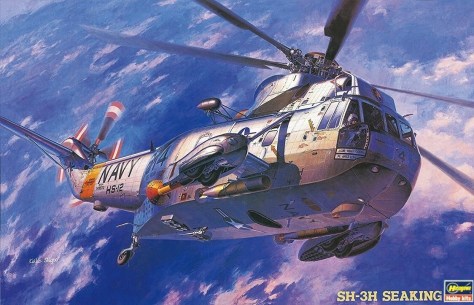
After all the scratch building and revision work on my Apollo Recovery SH-3D Sea King, I decided I wanted to build something straight out of the box. With hindsight, this perhaps wasn’t the best choice from my stash—it’s not exactly a quick and easy build.
It’s is a resin and steel photo-etch kit from Fantastic Plastic, who specialize in science fiction models and unusual concept aircraft kits. The kit depicts Space Station V from the Stanley Kubrick’s classic film, 2001: A Space Odyssey (1968).
The business about “variable scale” on the box art just means that the kit includes three different sizes of the Orion space clipper, which is seen docking with the station in the film. Because Kubrick combine images of different models, it’s not clear what the exact ratio of sizes should be in “real life”.
How best to hover the model Orion in docking position is a matter for conjecture—I’ll come back to that in due course.
The kit comes with some fairly big chunks of resin, making up the body of the space station:
Click to enlarge
In the photo above, I’ve already prepared and glued the two parts that make up each of the two docking ports—a lot of work is required to get rid of the pour stubs so that these pieces come together properly. There’s also a right way up and a wrong way up to combine them—the correct positions give a nice smooth profile to the docking bays; the wrong positions produce an interior step. There are also some quite nasty pour stubs to be removed from the curved sections that make up the rim.
And finally, there are the spokes. These come with little “outrigger” sections moulded in, but these are fragile and easy to damage, and in fact were already damaged and incomplete when the kit arrived. So I made the decision to strip them all off and replace them, in due course, with some brass strip of matching dimensions. Here’s an example of one of the spokes with outriggers in place, and the brass strip I’ll use to replace them:
Click to enlarge
Another small problem was a missing corner from one of the short sections of partial rim, which I managed to patch up with some styrene sheet:
Click to enlarge
And so to start the assembly. I stared at the four rim sections, four spokes and the hub of the complete ring for a while, trying to figure out how to bring them together. The spokes come with stonking great locator studs at each end, which need a lot of filing and sanding to get them down to the size of the locating holes in hub and rim.
Having done that, I first got the spokes attached to the hub, using dry-fitted rim sections and the scale plans provided with the kit to get the alignment correct:
Click to enlarge
This was helped by the realization that the outer end of the spokes are just the right size to act as vertical spacers to lift the rim section into its correct location relative to the hub.
The rim sections needed a little work. Laying them on the plans revealed that they had all flexed slight since moulding, assuming the wrong curvature. That needed a few cycles of dipping in very hot water, applying pressure, and checking against the plans until the correct curvature was restored. (It made the plans a bit soggy.)
Getting the rim assembled around the spokes was complicated by the fact that there are two slim photoetch shapes that need to be slipped between the butt ends of the rim sections and around the outer ends of the spokes. I seemed to have too many degrees of freedom to control, bringing all these parts together at the same time. Eventually I decided to assemble it in sections.
Here are the first two rim sections, clamped with balsa to keep them planar, and with a sliver of styrene strip acting as a spacer for the eventual placement of the photoetch detail:
Click to enlarge
Also notice the photoetch parts already glued in place on the free ends of the two rim sections. These wrap around either side of the flared ends of the spokes, which is what complicates the assembly unconscionably.
Then I applied epoxy to the end of one spoke, and lowered the hub and spoke assembly into place, using the photoetch and sockets on the free ends of the rim section as a sort of jig to ensure everything lines up properly:
Click to enlarge
Leaving the ends of the transverse spokes free to slide in their locating sockets (I slightly shortened their ends to allow this), I then positioned and glued the remaining rim sections, with more balsa to keep the assembly planar:
Click to enlarge
Once that had dried, I could gently closed the gap at the top around the spoke and photoetch, completing the rim. Finally, with all the glue set and the clamps removed, I slotted the remaining photoetch into place in the gap I’d created with my spacers at the start of the process.
Click to enlarge
I’m sure there are countless other ways to achieve the same result, but this one worked for me, and the final result needed only a smidgeon of filler and tidying up.
Then I moved on to assemble the resin parts for the incomplete ring. Hub and spokes came together using the plans for alignment and a suitably stripped pad of writing paper to provide a support of the right height to keep the ends of the spokes in the correct plane while the glue set.
The resin parts are tricky, because they are of different shapes and need to be positioned correctly to match the plans:
Click to enlarge
I attached the photoetch to the butt of one section in each pair, closing it around the corresponding spoke and fixing with cyanoacrylate. Then I applied epoxy to fix the correct parts around each spoke, and left the whole lot to dry supported on paint pots to maintain the plane:
Click to enlarge
That’s all the resin assembled. Next time, I’ll start adding a very large amount of photoetch.
With the main bodywork of the aircraft completed last time, I finally got her standing on her undercarriage, in the form a set of ResKit resin wheels—slightly more detailed than the kit parts, with a nice open fork for the rear wheel.
The kit parts for the undercarriage legs need a very slight modification. They come as an interchangeable pair, but they were in fact slightly asymmetrical, with tie-down lugs only on the outside of each leg. A little work with a scalpel removed the unrealistic inner lugs, and then I just needed to remember to put the legs on the appropriate side of the aircraft.
Click to enlarge
Then it was time for the rotors. I painted the red and white warning stripes on the tail rotor, and the yellow tips to the main rotor, but resorted to printing up my own decals for the yellow stripes on the rotor blades.
Click to enlargeClick to enlarge
I wanted to model the main rotor folded, because I’m aiming for the appearance of this helicopter at a very specific moment in its career—at about 07:55 GMT on 24 July 1969, just after landing on the deck of the USS Hornet with the Apollo 11 astronauts on board, while being towed to the elevator to descend into the hangar bay.
Click to enlarge Screen capture from Apollo 11 documentary film
With the rotors test-fitted, I removed them while I added all the fiddly surface detail needed to make the helicopter come alive. I added a length of cable and a sling to the kit’s winch, so that I could reproduce the partially stowed position in the view above.
I added my scratch built camera mounts and the SARAH yagi antennae, which had been languishing in a pot for safe-keeping during the whole build process. I belatedly realized that I had planned to place the forward camera in the wrong place on the forward weapons mount points. I’d aimed to place it on the forward position of these two points, tucked under the horizontal sponson support. But a late find of an underside view of this aircraft (during the Apollo 10 recovery) convinced be that the camera needs to be on the aft position, behind the sponson support, where it’s clearly visible in the photo. That meant a little work with a scalpel and some touch-up paint, and the rerouting of the forward camera cable-run in its last few millimetres, but it was fairly painlessly accomplished.
And I put together a rotor retainer sling from styrene and painted paper, to restrain the two outermost folded rotors. You can see it in the image above, and there’s additional detail visible in hangar-bay views like this one:
And I rigged the radio antennae on both sides of the fuselage, placing the kit mounting pylons in locations gleaned from the aircraft photographs, and then running stretched sprue between them to reproduce the run of the aerial wire. The underside view I linked to earlier was particularly useful in judging the length of the pylons, and from peering at various other photographs, this is what I came up with:
Click to enlargeClick to enlarge
Open dots are mounting pylons, closed dots are points where wires join (on the starboard side, a short length of wire appears to come out of the fuselage and link to a simple span of wire between two end pylons.)
By the time I was placing cockpit mirrors and pitot tubes, I was beginning to run out of places to hold the model.
Here’s the final result:
Click to enlargeClick to enlargeClick to enlargeClick to enlargeClick to enlargeClick to enlargeClick to enlargeClick to enlargeClick to enlarge
At the end of the my previous post in this build log, I was just about ready to glue the big bits of fuselage together. Which went surprisingly well. The cockpit canopy comes in three sections, and that went less well—the side windows were awkward to align properly, and both of them made brief excursions inside the fuselage tube before I managed to get them in approximately the correct positions.
Then there were a few more bits and pieces to assemble in the engine area before an all-over coat of white, followed by some masking to add the underside coat of Light Gull Grey and the black patch behind the engine exhaust. (This black patch comes in a myriad of different shapes and sizes on different Sea Kings, so I checked mine against photographs of the real thing.)
Here she is, with the basic livery applied.
Click to enlargeClick to enlarge
And here with all the paint detail applied—blue markings around the tail, red around fuelling points, some black window frames:
Click to enlarge
At this point, I added an odd little detail specific to sea-faring versions of this helicopter—a rope that runs from an eye-ring below the cockpit to a point just beside the port-side window:
(I copied the above image of Old 66, late in her career, from the excellent article by Jodie Peeler at Tailhook Topics, which covers the various changes in the appearance of this helicopter during its Apollo recovery days.)
Again, the good people at Britmodeller came to my rescue, explaining that this is the attachment for a sea anchor, should the helicopter have to ditch in water. The sea anchor, streamed from the nose of the aircraft, would slow its drift and keep the nose pointing into wind.
Here’s my version:
Click to enlarge
And then, the decals. US Navy helicopters were intricately marked with information panels and warning arrows, and there was much variation between aircraft. The Starfighter decal set provides the basic numbers and letters and a few of the more prominent details, but doesn’t do all the fiddly bits. The Hasegawa SH-3H kit provides many information panels for three completely different helicopters—but there’s enough overlap to allow me to dissect out useful bits and pieces and apply them in locations identified from photographs of “Old 66” itself. (Here, I ran into the problem that the starboard side of this aircraft is, for various reasons, much better documented than the port side. So some of my port-side markings were applied on the basis of assuming symmetry between the two sides.)
The Hasegawa decals were robust to the point of chunkiness. In contrast, the Starfighter decals were delicate, verging on fragile, but bedded down beautifully to give the necessary “painted on” look. Unfortunately, the Starfighter red pigment was disappointingly faded and blotched in the sheet I used, with some of the detail obscure and the warning colours appearing as a sort of chestnut brown rather than a vivid red.
On the starboard side, I added strips of my own yellow decal to reproduce the bright protective tape that was used to secure the front and rear camera cables. I also added a little styrene placard to reproduce the “Now Hornet Plus Three” notice that was mounted on the side of the cockpit as soon as the helicopter landed on the USS Hornet, carrying its three astronaut passengers:
Starfighter’s markings chart errs with regard to the yellow tape, suggesting a length of it ran forward along the lower side-door slide to link up with the tape around the side window frame. There’s no sign of this in photographs of the real aircraft, and it would in any case have run the risk of fouling the door or damaging the cable. I presume the folks at Starfighter thought that the cable from the rear camera ran all the way forward to enter the fuselage above the side window frame. But in fact the rear camera cables entered through the side door, and the side window cable-run was associated with the forward camera mount, as I’ve depicted.
On the port side, there’s another problem with Starfighter’s decals—not enough “Rescue” arrows, and a wrongly positioned arrow on their marking chart.
I used the Hasegawa SH-3D box art photograph as my reference. It depicts this side of the aircraft as it was during the months between the Apollo 11 and Apollo 12 recoveries:
Click to enlarge
And here’s my version:
There were three “Rescue” arrows grouped around the door (one at a slightly different angle from the other two), and a fourth horizontal arrow behind the side window. (I used a decal from the Hasegawa kit to provide the necessary fourth arrow.)
For the underside, Starfighter provides the “Hail Columbia” welcome sign painted beneath the side door, where the astronauts could see it as they were winched aboard.
Click to enlarge
And this is the point at which my Britmodeller advisers pointed out to me that I shouldn’t have followed the kit instructions, removing the octagonal antennae on the underside. They were definitely present in the aircraft I’m modelling—they can be seen in a rare blurry underside shot taken during the Apollo 10 recovery.
Also visible in that view is another circular antenna just forward of the red warning light. So not only did I need to scratch-build the circular antenna, I had to reconstruct the octagonal antennae that I’d mistakenly removed.
The circular antenna I built from styrene sheet, using a couple of appropriately sized hole punches to make the base and frame. For the octagonal antennae, I got some use out of the lying kit instruction sheet—I printed out the relevant section to scale, glued it to a sheet of styrene, and cut out the octagonal shapes using the kit plan as a template.I could have saved myself a bit of time if I’d just properly researched these features in the first place, though.
Finally, a little bit of light weathering to emphasize panel lines and give the appearance of an aircraft that had been flying long hours in practice for the weeks before the actual recovery. And then I mounted the two sponsons on either side, which I’d kept to one side until I had most of the fuselage detailing done.
Click to enlargeClick to enlargeClick to enlarge
You can see my restored antennae on the underside.
Next time—undercarriage, rotors and some fiddly detail.
In my last post, I still had a few bits and pieces of scratch building to do—a stills camera tucked behind the starboard sponson, facing backwards, and some weapons mount points.
I haven’t been able to find any good views of the stills camera beyond a couple of glimpses in Todd Douglas Miller’s Apollo 11 documentary:
What does seem to be the case is that (in contrast to the rear pairs) the paired forward mount points weren’t in use beyond the single camera mount. So I put together an “artist’s impression” of a stills camera on a mount, swathed in the ubiquitous yellow tape, and I cannibalized the kit’s forward weapon mounts to build the necessary rear mounts, looking something like what I can see in photographs. It’s all a little unsatisfactory, but it’s the best I could come up with.
Click to enlarge
I also spent a little time getting the Belcher Bits resin sponsons mated to the kit parts. These are very nicely moulded, and just need the locating holes for the upper sponson struts to be drilled a little deeper, and bit of chiselling and filling around the lower supports. Here they are, taped in place while waiting for the epoxy to dry:
Click to enlarge
I have a suspicion the final alignment may make the undercarriage a little “in-toed” but I can cross that bridge when I come to it.
And here they are, filled and primed:
Click to enlarge
I’m going to paint them separately and only attach them late in the build process.
The Hasegawa SH-3D instruction sheet I downloaded from Scalemates wants me to attach something to the back underside of the starboard sponson—it’s made of two pieces from sprues that don’t come with the SH-3H kit.
But a look at images of the real helicopter show no external feature in this location:
The good people over at Britmodeller tell me that this is, in fact, a recessed spotlight in a square well. I doubt if I can create such a thing successfully by burrowing into a solid resin part, so I’ll try to suggest its presence with paint instead.
Another object that isn’t included in the SH-3H kit but which was present in the real helicopter is a fin of some kind on the underside, which I scratch-built for styrene card. While I was at it, I scratch built another little fin for the underside. This one was include in the kit, but departed from my tweezers towards parts unknown almost as soon as I freed it from the sprue. Here’s the underside with fins added, the blanked sonar well in place, and all the various bumps and ridges detailed in my last post removed:
Click to enlarge
Another little challenge on the underside of the model are three small light fittings, for which there are no paint masks on the Montex sheet. I’m not very good at cutting tiny discs out of masking tape, and after a bit of thought I put a strip of Tamiya tape on to an offcut of styrene sheet, and punched out some suitable sized holes with a leather punch. After a few attempts, I ended up with some neat masking discs I could peel off the punched-out styrene and put in place:
Click to enlarge
Now I just need to remember to remove them once the model is completed.
As well as removing lumps and bumps from the port fuselage I had to get rid of the window just aft of the door. I glued the transparent part in place and then filled and sanded the outside. If I was doing it again I’d sand off the window frame (moulded into the transparent part) before putting the window in place—that would have made filling and sanding easier. The final result looks OK after a light coat of grey primer:
Click to enlarge
On the starboard side, more lumps and bumps were removed, and I added the two runs of cable that will eventually connect to my two scratch-built camera mounts:
Click to enlarge
That’s it for now. It seems like a lot of work for little progress, but next time things should actually start looking like a helicopter.
In my previous post on this topic, I described how flight engineers working on the Apollo programme assigned XYZ coordinate axes to the Saturn V launch vehicle and to the two Apollo spacecraft, the Command/Service Module (CSM) and the Lunar Module (LM). This time, I’m going to talk about how these axes came into play when the launch vehicle and spacecraft were in motion. At various times during an Apollo mission, they would need to orientate themselves with an axis pointing in a specific direction, or rotate around an axis so as to point in a new direction. These axial rotations were designated roll, pitch and yaw, and the names were assigned in a way that would be familiar to the astronauts from their pilot training. To pitch an aircraft, you move the nose up or down; to yaw, you move the nose to the left or right; and to roll, you rotate around the long axis of the vehicle.
These concepts translated most easily to the axes of the CSM (note the windows on the upper right surface of the conical Command Module, which indicate the orientation of the astronauts while “flying” the spacecraft):
With the astronauts’ feet pointing in the +Z direction as they looked out of the windows on the -Z side of the spacecraft, they could pitch the craft by rotating it around the Y axis, yaw around the Z axis, and roll around the X axis.
The rotation axes of the LM were similarly defined by the position of the astronauts:
Looking out of the windows in the +Z direction, with their heads pointing towards +X, they yawed the LM around the X axis, pitched it around the Y axis, and rolled it around the Z axis.
For the Saturn V, the roll axis was obviously along the length of the vehicle, its X axis.
But how do you decide which is pitch and which is yaw, in a vehicle that is superficially rotationally symmetrical? It turns out that the Saturn V was designed with a side that was intended to point down—its downrange side, marked by the +Z axis, which pointed due east when the vehicle was on the launch pad. This is the direction in which the space vehicle would travel after launch, in order to push the Apollo spacecraft into orbit—and to do that it needed to tilt over as it ascended, until its engines were pointing west and accelerating it eastwards. So the +Z side gradually became the down side of the vehicle, and various telemetry antennae were positioned on that side so that they could communicate with the ground. You’ll therefore sometimes see this side referred to as the “belly” of the space vehicle. And with +Z marking the belly, we can now tell that the vehicle will pitch around the Y axis, and yaw around the Z axis.
If you have read my previous post on this topic, you’ll know that the astronauts lay on their couches on the launch pad with their heads pointing east.* So as the space vehicle “pitched over” around its Y axis, turning its belly towards the ground, the astronauts ended up with their heads pointing downwards, all the way to orbit. This was done deliberately, so that they could have a view of the horizon during this crucial period.
But the first thing the Saturn V did, within a second of starting to rise from the launch pad, was yaw. It pivoted through a degree or so around its Z axis, tilting southwards and away from the Launch Umbilical Tower on its north side. Here you can see the Apollo 13 space vehicle in the middle of its yaw manoeuvre:
This was carried out so as to nudge the vehicle clear of any umbilical arms on the tower that had failed to retract.
Then, once clear of the tower, the vehicle rolled, turning on its vertical X axis. This manoeuvre was carried out because, although the belly of the Saturn V pointed east, the launch azimuth could actually be anything from 72º to 108º, depending on the timing of the launch within the launch window. (See my post on How Apollo Got To The Moon for more about that.) Here’s an aerial view of the two pads at Launch Complex 39, from which the Apollo missions departed, showing the relevant directions:
An Apollo launch which departed at the start of the launch window would be directed along an azimuth close to 72º, and so needed to roll anticlockwise (seen from above) through 18º to bring its +Z axis into alignment with the correct azimuth, before starting to pitch over and accelerate out over the Atlantic.
Once in orbit, the S-IVB stage continued to orientate with its belly towards the Earth, so that the astronauts could see the Earth and horizon from their capsule windows. This orientation was maintained right through to Trans-Lunar Injection (TLI), which sent the spacecraft on their way to the moon.
During the two hours after TLI, the CSM performed a complicated Transposition, Docking and Extraction manoeuvre, in which it turned around, docked nose to “roof” with the LM, and pulled the LM away from the S-IVB.
This meant that the X axes of CSM and LM were now aligned but opposed—their +X axes pointing towards each other. But they were also oddly rotated relative to each other. Here’s a picture from Apollo 9, taken by Rusty Schweickart, who was outside the LM hatch looking towards the CSM, where David Scott was standing up in the open Command Module hatch.
The Z axes of the two spacecraft are not aligned, nor are they at right angles to each other. In fact, the angle between the CSM’s -Z axis and the LM’s +Z axis is 60º. This odd relative rotation meant that, during docking, the Command Module Pilot, sitting in the left-hand seat of the Command Module and looking out of the left-hand docking window, had a direct line of sight to the docking target on the LM’s “roof”, directly to the left of the LM’s docking port.
Once the spacecraft were safely docked, roll thrusters on the CSM were fired to make them start rotating around their shared X axis. This was called the “barbecue roll” (formally, Passive Thermal Control), because it distributed solar heating evenly by preventing the sun shining continuously on one side of the spacecraft.
Once in lunar orbit, the LM separated from the CSM and began its powered descent to the lunar surface.† This was essentially the reverse of the process by which the Saturn V pushed the Apollo stack into Earth orbit. Initially, the LM had to fire its descent engine in the direction in which it was orbiting, so as to cancel its orbital velocity and begin its descent. So its -X axis had to be pointed ahead and horizontally. During this phase the Apollo 11 astronauts chose to point their +Z axis towards the lunar surface, so that they could observe landmarks through their windows—they were flying feet-first and face-down. Later in the descent, as its forward velocity decreased, the LM needed to rotate to assume an ever more upright position (-X axis down) until it came to a hover and descended vertically to the lunar surface. So later in the powered descent, Armstrong and Aldrin had to roll the LM around its X axis into a “windows up” position, facing the sky. Then, as the LM gradually pitched into the vertical position, with its -X axis down, the +Z axis rotated to face forward, giving the astronauts the necessary view ahead towards their landing zone.
Click to enlarge The LM pitches towards the vertical as it descends (NASA TM X-58040)
Finally, at the end of the mission, the XYZ axes turn out to be important for the re-entry of the Command Module (CM) into the Earth’s atmosphere. The CM hit the atmosphere blunt-end first, descending at an angle of about 6º to the horizontal. But it was also tilted slightly relative to the local airflow, with the +Z edge of its basal heat-shield a little ahead of the -Z edge. This tilt occurred because the centre of mass of the CM was deliberately offset very slightly in the +Z direction, so that the airflow pushed the CM into a slightly tilted position. This tilt, in turn, generated a bit of lift in the +Z direction—which made the Command Module steerable. It entered the atmosphere with its +Z axis pointing upwards (and the astronauts head-down, again, with a view of the horizon through their windows). The upward-directed lift prevented the CM diving into thicker atmosphere too early, and reduced the rate of heating from atmospheric compression.
Click to enlarge
Later in re-entry, the astronauts could use their roll thrusters to rotate the spacecraft around its X axis, using lift to steer the spacecraft right or left, or even rolling it through 180º so as to direct lift downwards, steepening their descent if they were in danger of overshooting their landing zone.
* As described in my previous post on this topic, the coordinate axes of the CSM were rotated 180º relative to those of the Saturn V—the astronauts’ heads pointed in the -Z direction of the CSM, but the +Z direction of the Saturn V.
† I’m missing out a couple of steps here, in an effort to be succinct. (I know, I know … that’s not like me. Take a look at NASA Technical Memorandum X-58040 if you want to know all the details.)
Trouble is, 1/48 scale kits for the SH-3D version of the Sea King are rare and correspondingly expensive. But there is a fairly well-trodden route involving the conversion of an SH-3H, such as the Hasegawa one I’m using here.
So I’ve got the kit, and the decals. I also have a set of short SH-3D-style sponsons (to replace the long SH-3H versions) from Belcher Bits, a set of Montex paint masks for the windows and cockpit canopy, and the instruction sheet for the rare Hasegawa SH-3D kit, downloaded from Scalemates. And, it turns out when I open the Hasegawa box I bought on eBay, I also have a set of QuickBoost resin replacement seats and an Eduard photoetch cockpit detail set. This is the second time I’ve found extras squirrelled away inside a second-hand kit, which kind of compensates for the times I’ve found parts missing from other eBay kits.
First up, some of the kit parts require modification. Hasegawa’s SH-3D kit used the same fuselage parts as the SH-3H, so it provides some good information on which of the kit’s various lumps and bumps need to be removed. There’s also the small matter of a window that needs to be filled on the port side.
Click to enlargeClick to enlarge
Note: Here I need to intrude with the benefit of hindsight, to say that the SH-3D instructions are wrong when they indicate the removal of the two raised octagonal structures on the underside of the aircraft. These aerials are visible in photographs of the real thing, and should be left in place. Later in this build log I’ll report on how I had to build replacements, having dutifully removed the originals.
Then the horizontal stabilizer needs to be shortened and its supporting strut discarded, with the locating holes filled.
Click to enlarge
I rounded the end of the shortened stabilizer with a little filler.
I also needed to remove the dipping sonar from its well on the underside of the aircraft. The well and the tip of the sonar probe come moulded as a single part from Hasegawa, so I sawed them apart.
Click to enlarge
I’ll blank off the sonar well with some styrene sheet—it was blanked at floor level in the real aircraft, too.
Next, there’s some scratch building. The Gemini and Apollo recovery helicopters were fitted with a rack of cameras, attached to the aft weapon mount point on the starboard side, to film and photograph the recovery process. Todd Douglas Miller’s excellent documentary, Apollo 11, provided some good views of this object. Here are three screen grabs from that film, together with a blurry detail from a more distant photograph:
Click to enlarge Views of the camera mount for Apollo 11 recovery. Lower right, detail from NASA S-69-21723; remaining images screen captures from Apollo 11 documentary film
There was a lot of sticky-tape engineering involved. Starfighter decals provide a yellow strip to help reproduce this appearance, but to my eye it’s too orange, so I printed up my own decal sheet to produce the necessary strips of colour.
Here’s the final result for the camera mount, cobbled together from bits of styrene and half-millimetre brass rod:
Click to enlargeClick to enlarge
Also required is a pair of Search And Rescue Homing antennae, mounted on the sponson struts. Here they are in a view of the Apollo 8 recovery:
And here’s my effort using styrene, brass rod and stretched sprue:
Click to enlarge
I’ve also got a couple of pending jobs. There was also a stills camera mounted behind the starboard sponson, pointing aft, presumably attached to a forward weapon mount point, but I’ve yet to discover any kind of detailed view of this. And it’s clear from the camera-mount photographs that a weapon mount was still in place just forward of the camera mount; a pair were also in place on the other side of the aircraft, as can be seen from the Hasegawa SH-3D box art photograph:
Click to enlarge
These are different from the parts provided in the kit, and I’m going to need to scratch build them, too. And again, decent photographs are difficult to find.
But in the meantime, I’ve assembled the cockpit. This is SH-3H in detail, but I figured that if I tried to revise the appearance, I’d end up with something that looked much less effective, and which in any case would be poorly seen through the kit canopy:
Click to enlargeClick to enlarge
I also masked up and painted the interior of the canopy, including the green-tinted top windows. This last part was done using Tamiya Clear Green, which I found a bit of a bugger to spray evenly.
Click to enlarge
In the next instalment, I’ll start putting some of these parts together.
 And I probably should have researched this a little better before I started work. When I started out on this project, I recalled the livery as being pale grey with random dark grey streaks, but when I rewatched the 4:3 pan-and-scan DVD which represents the film’s only English-language release, it became evident that the upper surfaces and under-wings were patterned with a stylized pattern of feathers.

 Oops. So it was time to start printing some custom decals, producing my best “artist’s impression” of the patterns on the original aircraft, using only the blurry views available from the DVD.


 That doesn’t really reflect the subtle shading of the station depicted in the film:


 This gave me a “realistic” reason to have something connecting the back of the Orion to the station docking port—a drive plume, of some sort, as in McCall’s painting.


 I could have saved myself a bit of time if I’d just properly researched these features in the first place, though.