Category Archives: Building

Tamiya 1/48 P-47D Thunderbolt “Razorback”: Part 2

So last time I had completed priming, and had masked off the SEAC white identification stripes.

The next task was to apply the camouflage colours of the Temperate Land Scheme—Medium Sea Grey undersides, and an RAF standard pattern of Dark Earth and Dark Green above. It’s always a puzzle how sharp-edged the camouflage patterns should be. Some patterns were reputedly applied using large paint masks, and so could be expected to be extremely sharp-edged at 1/48 scale. On the other hand, if camouflage was applied free-hand with a spray gun, one could expect to see softer edges, even at 1/48 scale. Looking at contemporary photographs wasn’t much help—some of the patterns on RAF Thunderbolts seemed to be very sharply defined, while others were very diffuse. So I decided I’d try for a softer edge by placing my masking a millimetre or so above the surface of the model, in an effort to simulate the effects of a free-hand spray job.

After painting the underside, I applied Dark Earth to the upper parts, and then laid on paper masks supported by thin rolls of Blu Tack. After an immense amount of fussing around getting the paper edges a reasonably uniform distance from the surface of the model, I sprayed on Dark Green. I had to keep reminding myself to keep the spray as much as possible at right angles to the edges of the masks—the last thing I wanted was to spray under the mask and get a thick line of pooled paint along the edge of the Blu Tack.

Masking Tamiya 1/48 Thunderbolt for camouflage
Click to enlarge

But this technique certainly removes a lot of the anxieties about paint leaking under the masking by capillary action. Except, of course, for my white SEAC stripes, with their closely applied masking tape—the white would show up any masking leaks all too noticeably. So there was the customary flicker of anxiety as I started to peel off all the layers of paper and Blu Tack and tape. But it worked out pretty well—a couple of tiny trickles along a couple of panel lines were swiftly removed using a little gentle pressure from a wooden cocktail stick, which didn’t disturb the underlying white paint. Then the whole thing was coated with gloss varnish, ready for the decals.

Tamiya 1/48 Thunderbolt, SEAC colours
Click to enlarge

SEAC markings are surprisingly difficult to come by—those unobtrusive little Dull Blue and Light Blue roundels seem to be unpopular with model builders. I’ve previously had an unfortunate experience with a rather elderly set of SEAC decals, bought on eBay, which leaked some unpleasant gunk on to the paintwork while simultaneously refusing to bed down properly. But this time I was well served by Xtradecal’s sheet X48115—variously called “P-47D Thunderbolt in RAF/SEAC Service” or “Yanks with Roundels Part 4”. This not only gave me the roundels and flashes I needed, but as a bonus had the tail serial number for HB982, the aircraft immediately after mine in the RAF code sequence. With a “1” stolen from another set of codes, I was able to assemble the serial number I wanted using only two decals, rather than going through the usual performance of teasing five individual characters into alignment.

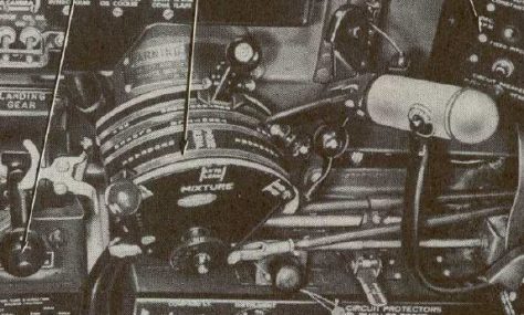
The WK-H squadron letters for this aircraft posed another. The official Temperate Land Scheme required code letters to be marked in Sky—a sort of duck-egg green shade. However, according to Geoff Thomas’s book, squadrons tended to mix their own paint from Dull Blue and White, “the resulting colours varying from Deep Sky to light grey-blue”. I’ve yet to find a colour photograph showing this, and looking at black and white photographs is of course no help at all. Here’s a 135 Squadron aircraft from a little earlier in the war:

135 squadron Thunderbolts
Click to enlarge
© Imperial War Museum (CF 1242)

Are those code letters pale grey-blue or duck-egg green?

The problem was resolved for me, though not to my particular satisfaction, by how difficult it was to obtain RAF letters of the right size (18″) in any shade but Sky. Although pale blue letters are available for particular aircraft on the Xtradecal sheet, they didn’t match what I needed, and I couldn’t track down any white letters of the right size, which I could have tinted. A truly dedicated model maker would have produced his own stencils and sprayed the letters on, or printed them on to white decal backing and cut them out, and I actively considered those options for a while, before deciding that whatever I did, it would not be a match for the unknown original appearance. So I went with the standard Temperate Land Scheme—the letters I used are from Fantasy Printshop.

Tamiya 1/48 Thunderbolt, SEAC colours and markings
Click to enlarge

I added the various small stencils for fuel fillers and electrical connections supplied with the Tamiya decal sheet. I couldn’t find any photographs suggesting that a red “No Step” panel on the inboard flaps were used in RAF SEAC aircraft, so I replaced the panel provided on the Tamiya decal sheet with a plain stencil from my decal cache.

Once the decals had bedded in and dried thoroughly, I added another coat of gloss varnish and started marking up the (many, many) panel lines. As with previous kits, I used Lifecolor’s Liquid Pigment for this. It settles neatly into the engraved lines of the kit, and any excess can be removed (even when dry) with Lifecolor’s removal fluid. Careful wiping of partially removed pigment produces a nice preliminary weathering of the aircraft’s surface. The main trick to using this stuff is to keep shaking the bottle—it settles out very quickly, so the black liner will slowly turn blue if you don’t keep remixing the pigment.

Once that had dried, I applied a couple of coats of matt varnish, ready for final weathering and the addition of final bits and pieces like the undercarriage, propeller, guns and external fuel tanks.

Tamiya 1/48 Thunderbolt, SEAC colours and markings, panel lines
Click to enlarge
Tamiya 1/48 Thunderbolt, SEAC colours and markings, panel lines underside
Click to enlarge

And that’s where I’ll pick up next time.

Tamiya 1/48 P-47D Thunderbolt “Razorback”: Part 1

Tamiya 1/48 P-47D RazorbackI’m using the Tamiya kit to model a specific aircraft, again. This is going to be a Republic P-47D-22-RE Thunderbolt, on the complement of 135 Squadron RAF in Burma from April to May 1945. Its American serial number was 42-25818, with a British serial of HB981. It was what the RAF called a “Thunderbolt I”—what’s commonly referred to as a “razorback”, to distinguish it from the later “bubbletop” models, which the RAF designated the “Thunderbolt II”.

It met its end at Akyab airfield, damaged beyond repair, on 2 May 1945, when it lost power on take-off, crashing and ground-looping some distance beyond the end of the runway. The squadron Operation Record Book has a laconic record of the event:

135 Squadron Operation Record book 2/5/45
Click to enlarge

I’ll fill in a bit more detail as we go along.

The Tamiya kit is nominally a P-47D-20, but includes the parts I needed to make the one big change necessary to turn it into a P-47D-22 version—a larger propeller. The RE code indicates that my aeroplane was built at the factory in Farmingdale, Long Island, which fitted Hamilton Standard propellers to their block 22 aircraft. Despite the fact it’s not called for in the kit assembly instructions, a Hamilton propeller is actually included on the kit sprue, with appropriate maker’s marks on the decal sheet, too.

This is my first Tamiya kit, and I have to say I’m seriously impressed. Coming to it after my recent forays into ancient Revell, Airfix and Lindberg toolings, it’s a joy to work with parts that just fit together properly, and mouldings that place the gates in sensible places (rather than slap in the middle of a complicated and highly visible surface).

I added a couple of photoetched sets from Eduard—their P-47D-20 detailing kit, and their P-47D placards. There’s a bit of overlap between these two sets, but they each included something I wanted. I also needed to track down a 1/48 scale Sutton harness—the RAF reportedly (though there’s some debate) replaced the American-style harness in American aircraft with their own standard type. I settled on a “fabric” version from HGW Models, which looked promising but caused me a fair number of problems.

The Tamiya cockpit is nicely detailed, and fits together perfectly. I slightly vandalized it by accidentally setting my airbrush at too high an operating pressure for my Alclad primer, lending the surfaces a slightly pebble-dashed appearance that shows up rather too well in the detailed photos that follow, particularly the bright metal areas. Trying to strip off a laquer layer seemed like too dangerous an enterprise, and the result will anyway be much less visible inside the assembled cockpit, when the light necessarily comes from within a pretty narrow angle to the viewing direction.

I added the Eduard cockpit placards and instrument panel, and a selection of levers and nobs. The HGW harness seems to be made of some sort of stretchy neoprene, admirably detailed, and supposedly thin enough to thread through the various photoetched buckles provided. It comes on a white backing paper. When I tried to remove this, a couple of straps separated into sections; when I tried leaving it in place, it proved too thick to thread through the buckles properly. Eventually I used parts of two harness sets to produce one slightly bodged final result.

Tamiya P-47D cockpit 1
Click to enlarge
Tamiya P-47D cockpit 2
Click to enlarge
Tamiya P-47D cockpit 3
Click to enlarge

I made one modification to the Eduard detail—revising the throttle lever with a couple of plastic strips to produce the brown-and-white object that looks a little like an ice-lolly sticking up from the left side of the cockpit. I’m not entirely sure about this. The P-47 throttle lever went through at least three iterations during production, shown below in details taken from various pilot’s manuals.

P-47D quadrant 1

P-47D quadrant 2

P-47D quadrant 3

The reference works I have are inconsistent with each other, and the manuals sometimes show more than one style of quadrant. Eventually I made a “best guess” to model the middle illustration above, with a large vertical throttle handle supporting a water-injection switch on its top.

Next, the engine. The Hurricanes I’ve been modelling had their engines decently concealed, but the Thunderbolt had a fair part of its complicated air-cooled radial engine on display. The Tamiya kit provides parts for the front half of the engine (all that’s visible in an intact aircraft), to which I added a photoetched ignition harness from the Eduard detailing set. Here it is, during a trial fit, which also demonstrates the lovely moulding Tamiya produces:

Tamiya Pratt & Whitney with Eduard armature
Click to enlarge

It’s a challenging object, comprising 36 cables, each of which has to be connected to the front or back of one of the Pratt & Whitney R-2800’s eighteen cylinders.

That came after painting, weathering and detailing the kit engine. Here’s the final assembly, with ignition harness in place:

Tamiya Pratt & Whitney completed 2
Click to enlarge
Tamiya Pratt & Whitney completed 1
Click to enlarge

Notice the tiny Pratt & Whitney eagle logo on the front, provided by Eduard.

Then it was a matter of masking and priming the aircraft fuselage. I put the undercarriage covers in place with Blu Tack, to mask the wheel wells and prepare them for the underside paint. The cowling has a nice locating mechanism that means it’s easy to paint it separately and put it in place later. I’m also modelling this aircraft with flaps down, so they’re being primed and painted separately.

P-47 primer 1
Click to enlarge
P-47 primer 2
Click to enlarge

The white primer is chosen because this aircraft sported SEAC stripes—white identification markings on cowling, wings and tail adopted within the South East Asia Command area in 1945. I’ve left my primer a little thin—I didn’t want to layer the stuff on and obscure detail, and any slight variation in the lightness of the overlying paintwork will be compatible with the weathered appearance that’s evident in photographs. I’ve also sprayed the area of the SEAC stripes with a final coat of matt white, which I’ll then mask to protect it from the application of later camouflage paint. That’s a reversal of the order in which this paint would actually have been applied, but again I want to preserve surface detail by avoiding having to apply multiple layers of white on top of dark camouflage colours.

Cover of Royal Air Force ThunderboltsThere’s a bit of a problem with the SEAC stripes for this aeroplane. According to Geoff Thomas’s excellent reference book Royal Air Force Thunderbolts, HB981 was part of a batch delivered between 12 March and 12 May 1944. But it doesn’t appear in 135 Squadron’s Operations Record until 4 April 1945, despite the fact that from the end of the previous year they were operating other HB and HD aircraft delivered in the same time frame. Where had HB981 been prior to its arrival at 135 Squadron? Maybe with another squadron, or perhaps in store, ready to be dispensed as a replacement aircraft. James J. Halley’s history of the H* serials doesn’t list HB981 anywhere else but with 135 Sq., but there are often gaps in the record.

Cover of Royal Air Force Aircraft HA100-HZ999Why is any of this relevant to the SEAC stripes? Because they were first used at the very end of 1944, when the original Instruction stipulated that stripes should span the whole chord of the vertical and horizontal stabilizers. After a protest that this extra layer of paint might interfere with the operation of the control surfaces, a new Instruction was issued in March 1945, stating that the tail stripes should not impinge on the rudder or elevators.

SEAC stripes (from Royal Air Force Thunderbolts, Geoff Thomas)
Click to enlarge
Full-chord SEAC stripes

If HB981 had come straight from storage, it would have been painted up with the later pattern of SEAC stripes; but if it had been in operation earlier in the year, it might still sport the full-chord stripes on its tail. (Thomas says that some aircraft had their tail markings stripped and reapplied, but there are plenty of photographs showing full-chord stripes still in place, right up to the end of the war.)

79 Sq RAF, Meiktila, July 1945
Click to enlarge
79 Sq. RAF, Meiktila, July 1945. NV-B (third from right) still sports the full-chord SEAC tail stripe. (Photo R.C.B. Ashworth)

So, in the absence of contrary evidence, I decided to give HB981 the later pattern of stripes. I masked off the relevant areas, and then applied another thin layer of white around the edges of the masks, to try to ensure that the subsequent layers of camouflage paint don’t leak into the white areas.

P-47 SEAC masking
Click to enlarge

And that’s where I’ll pick up this build log, next time.

Lindberg 1/96 Moon Ship (Revised)

This is a rickety old kit, first issued in 1958 by Lindberg. The version I’m building is a nostalgic reissue by Round2. During its sixty-year history, it has undergone various metamorphoses: shifting its supposed scale between 1:96 and 1:200; changing its name from U.S. Moon Ship (1958) to Star Probe Space Shuttle (1980s) to Lunar Lander (1993) and then back to U.S. Moon Ship (2013); and being issued by at least three different companies—Lindberg, Glencoe and Round2.

Multiple box art for Linberg Moon Ship
Click to enlarge

My interest stems from the fact it was based on a real design by Wernher von Braun, dating from the early 1950s, for a projected flight around the moon. A diagram of von Braun’s original conception appeared in the book Across The Space Frontier (1952), which I’ve previously reviewed. Von Braun’s plan involved assembling the 80-foot-long craft in orbit.

Click to enlarge

Chesley Bonestell produced a painting of the craft for a Collier’s magazine article published in March 1952, which was reproduced in Across The Space Frontier.

Click to enlarge

For reasons unknown, Lindberg decided to stick a set of landing legs on it, and to remove the crew access module from the personnel sphere, replacing it with an oddly sculpted but apparently functionless base. Even if this thing could land on the moon, the crew would be trapped in their quarters at the top of the stack, with no way to get out, let alone down to the surface.Detail of box art, Lindberg Moon Ship

Lindberg also added some strange red domes to cover the portholes, and discarded the hydrogen peroxide torus at the base of the stack.

So I wanted to migrate this lunatic Lindberg confection some way back towards von Braun’s original idea.

The first thing I did was chop the legs off.

Framework for Lindberg Moon Ship
Click to enlarge
Framework for Lindberg Moon Ship, minus legs
Click to enlarge

Then I sawed the sculpted base off the personnel module, and replaced it with a scratch-built airlock, built from 20mm pipe and styrene card.

Modified crew compartment, Lindberg Moon Ship
Click to enlarge

Finally (and miraculously) I discovered that two inches is a standard diameter for the sort of large curtain rings that slides along a pole, and that a two-inch ring fitted neatly into the base of the model framework. All I had to do was remove the eyelet from the ring, and I had my peroxide tank!

Two-inch curtain ring
Click to enlarge
Two-inch curtain ring, modified for peroxide tank
Click to enlarge

The strange red plastic domes were discarded, and the strange red plastic rocket nozzles were primed and painted.

Clear parts, Lindberg Moon Ship
Click to enlarge

Then it was just a matter of assembling the small number of parts, and shifting the kit’s single nitrogen tank slightly to accommodate the larger volume of the airlock. I discarded or repurposed most of Lindberg’s selection of decals, which didn’t seem to make much sense, and put together a set of markings from my decal stash that I felt fitted the period better—including a 48-star American flag and some late-war aircraft lettering.

Lindberg Moon Ship, modified to von Braun concept
Click to enlarge

It’s not a perfect reproduction of von Braun’s concept, but at least it has most of the right parts in approximately the right order.

I wanted to show the spacecraft “in flight”, and I wanted to have an astronaut performing some sort of EVA, as in Bonestell’s painting. So I found an old Airfix stand to attach the craft to, and I modified the legs of one of the kit’s standing astronaut figures to look more like someone working in free-fall. A length of 5-amp fuse wire (remember fuse wire?) provided the EVA tether.

Here’s the final result:

Moon Ship 12
Click to enlarge
Moon Ship 13
Click to enlarge
Moon Ship 9
Click to enlarge
Moon Ship 4
Click to enlarge
Moon Ship 10
Click to enlarge
Moon Ship 11
Click to enlarge
Moon Ship 8
Click to enlarge

Revell 1/96 Saturn V: S-IVB Aft Interstage

Having finished building the S-IVB third stage of my Saturn V, I moved on to the S-IVB Aft Interstage—a conical support structure that separated the 6.6m-diameter S-IVB above from the 10-m diameter S-II second stage below. The real thing was assembled into the Saturn V stack as part of the S-IVB, but after launch it remained attached to the spent S-II stage when the S-IVB engine fired. (At the moment of separation of the two stages, the interstage fired four solid fuel retro-rockets that nudged the S-II backwards away from the S-IVB.)

S-IVB and aft interstage
Click to enlarge
The S-IVB and its aft interstage (from the Saturn V Flight Manual: AS 503 (19MB pdf)

So you’d think a “building” instalment that involves finishing a single kit part wouldn’t be a problem. But you’d be wrong. The S-IVB Aft Interstage strikes fear into the heart of anyone who has ever painted a Saturn V model kit, because it involves painting horizontal black/white separations around the curve of a ribbed cone. The potential for paint masking to go horribly wrong is high.

There are other, Revell-specific problems. The first is (as with every stage of this model) just getting the orientation of the interstage right. The basic part is symmetrical—a simple conic frustum with four retro-rocket fairings evenly placed around it. But it needs to be painted with a pattern that is strongly asymmetrical—four quadrants each with their own black/white scheme. So its orientation needs to be judged from how it fits to the parts above and below.

The upper end of the interstage contains two locating studs intended to fit between flanges at the base of the S-IVB stage.

Original locator studs on Revell 1/96 S-IVB aft interstage
Click to enlarge

But there are a lot of flanges, the kit instruction booklet contains no diagram of the intended fit, and none of the possible orientations make any sense when compared to photographs of the real launch vehicle.

All but one of the slots between flanges are associated with locating points for kit parts to be applied to the S-IVB itself. The remaining slot is a little wider than the others, so it seems likely that it was intended to engage with the wider stud on the aft interstage.

Revell 1/96 S-IVB locator slot
Click to enlarge

After a little deliberation, I sanded off both studs, with the intention of placing one of my own later, to engage with this slot on the S-IVB.

The base of the kit interstage has flanges of its own, with a broad locating gap intended to engage with a pair of locating strips moulded into the forward skirt of the S-II kit part. So that looks promising. There are two visible landmarks on the kit’s S-II forward skirt—a notch that marks the location of the service tunnel, and a circular depression that marks the location of the liquid hydrogen vent pipes. Unfortunately, these two landmarks aren’t even properly aligned with each other, and neither of them is in a correct relationship with the axes of the interstage as defined by its retro-rocket fairings.

Revell 1/96 Saturn V - S-II forward skirt
Click to enlarge
S-II forward skirt

After checking with David Weeks’s jawdroppingly lovely Saturn V technical drawings, I sanded off the locating strips of my S-II forward skirt, and added styrene replacements 11/16″ (17 mm) to the right (as viewed from inside the skirt). This brings the S-II service tunnel into an appropriate orientation with the retro-rockets of the interstage, and I can deal with the LH2 vents as a separate issue when I get to that stage.

OK. With the relative orientation of the interstage and S-II nailed down, I now knew which quadrant of the interstage was which. Before I lost track of this, I scribed in a surface detail missing from the kit—a personnel access hatch that allowed workers to enter the interstage space. After measuring from Weeks’s drawings, I stuck Dymo Tape in place to act as a guide for my scribing tool. (Does anyone use Dymo Tape for its original purpose any more?)

Revell 1/96 Saturn V - scribing hatch on S-IVB aft interstage
Click to enlarge

Next I needed to think about the kit’s depiction of the retro-rocket fairings, which isn’t great. New Ware’s detailing set provides a set of resin replacement parts, which are slimmer than the kit detail, and include a moulded depiction of the detachable front covers of the fairings.

Revell 1/96 Saturn V - retrorocket fairing on S-IVB aft interstage + resin replacements
Click to enlarge

However, I would need to chisel out the moulded kit detail and refill smoothly around the resin replacements. After a bit of consideration, I decided not to risk the potential carnage I could wreak during such a replacement. Instead, I compromised by adding the front covers to the existing kit moulding, using epoxy resin and a little bit of masking tape.

Revell 1/96 Saturn V - adding cover to retrorocket fairing on S-IVB aft interstage
Click to enlarge
Adding the resin to the kit fairing
Revell 1/96 Saturn V - cover added to retrorocket fairing on S-IVB aft interstage
Click to enlarge
The final result

On, then, to the paint masking. Having sworn off using Bare-Metal Foil after my struggle with it while building the Instrument Unit, I suddenly became enamoured of it again. I couldn’t think of any better way to mask the corrugated surface created by the interstage stringers. So for the arc of the model that requires a black/white horizontal demarcation, I measured along the length of each stringer with a precut length of styrene strip, marked with a pencil, and then masked with an individually patch of Bare-Metal Foil, carefully bedded into the space on either side of the stringer using a tooth-pick and a cotton bud.

Revell 1/96 Saturn V - paint masking S-IVB aft interstage
Click to enlarge

The interstage was also marked with contrasting sway targets—little 2×2 checkerboards that allowed launchpad cameras to track any swaying of the launch vehicle. I masked these off, too, but ran into a couple of problems. The first is that the Revell kit’s stringers are notoriously overscale, and if I tried to stick to the correct size for the sway targets, they were just too distorted by the relatively large stringers and didn’t look square. So I ended up making them a little oversize, copying the dimensions of the sway target decals provided with the kit. The other problem is that David Weeks’s otherwise excellent technical drawings show two very slightly different positions for the sway target in quadrant B of the interstage—I didn’t notice this until after I’d masked and painted, and it looks like I chose the wrong diagram to follow.

The Bare-Metal Foil was as hard as ever to remove, and again needed a little white spirit to remove a dark residue from the white paintwork it had masked—but I got away without significant leaks, which was a major triumph.

Revell 1/96 Saturn V - S-IVB aft interstage (1)
Click to enlarge
Revell 1/96 Saturn V - S-IVB aft interstage (2)
Click to enlarge

With the interstage properly coloured, I put the S-IVB in place, correctly aligned, and made a light pencil mark where I needed to add a new locating stud to the interstage to register the flanges of the S-IVB stage correctly.

Revell 1/96 Saturn V - S-IVB and aft interstage
Click to enlarge

Tracing backwards through all the fiddling around to get things lined up, it turns out that the correct location is 1/8″ (3 mm) to the left of the slimmer original stud. So I needed to do this:

Moving locator studs on Revell 1/96 S-IVB aft interstage
Click to enlarge

to produce this:

Revised locating stud on Revell 1/96 S-IVB aft interstageAnd that was that. The Saturn V stack grows ever higher, but I’m going to take a break and do something else before I tackle the travesty that is Revell’s S-II stage.

Revell 1/96 Saturn V - Apollo stack, S-IVB and aft interstage
Click to enlarge

Note added retrospectively: After taking a look at a photograph of the Apollo 11 S-IVB being stacked, I revised the internal colour of this interstage to zinc chromate yellow.

Revell 1/96 Saturn V S-IVB aft interstage 2
Click to enlarge

Revell 1/96 Saturn V: S-IVB Stage

It’s been a while since I made any progress on this kit. Last time, I described building the Spacecraft/Lunar Module Adapter and Instrument Unit assembly. Moving down the launch vehicle, this time I’m building the S-IVB stage, which was the third stage of the Saturn V—the “small” one that pushed the Apollo stack into Earth orbit and then into translunar orbit.

The Revell kit has three parts for the main body of the S-IVB: moulded pieces representing the forward bulkhead and forward skirt; the aft bulkhead, thrust structure and aft skirt; and a printed piece of styrene card to connect the two, representing the hydrogen tank external wall. The styrene card is intended to be wrapped into a cylinder, and held together by a plastic strip representing the systems tunnel, which in the real rocket carried all the electrical connections between the aft and forward skirts—so it handily spans the full length between the two skirts.

Revell 1/96 Saturn V, S-IVB stage basic parts
Click to enlarge

There are a few problems with this basic assembly. One is that the styrene sheet is “helpfully” printed with the letters U S A. The only Saturn V S-IVB stage to be lettered in this way was the 500F Facilities Integration Vehicle, a dummy that never flew. (Unfortunately, that’s the Saturn V from which Revell derived the markings for its model, which it has never updated through numerous reissues.) So this needs to be flipped inside-out to conceal these markings. I blocked the locating holes with pieces of styrene card, so that they could be filled and sanded.

Revell 1/96 Saturn V, S-IVB stage styrene inside out
Click to enlarge

Another problem is that the moulded locating strips within the forward skirt, which fit into the Instrument Unit above, are (as I reported last time) out of place by about 10º, and need to be relocated so that the SIV-B is correctly aligned with the Apollo stack. The necessary displacement is by a quarter inch (six millimetres), to the right as you look at the inside of the skirt. This moves the systems tunnel of the S-IVB two scale feet to the right of the -Y marker on the Instrument Unit, and the same distance away from the Position II coordinate of the launch vehicle (which faces the launch tower).

Shift in locating strips for Revell 1/96 S-IVB stage
Click to enlarge

And finally, the systems tunnel provided in the kit is the wrong shape and size, and needs to be replaced—the replacement part being carefully aligned so that it conceals the seam in the styrene cylinder, above.

New Ware Saturn V Detail KitFor replacement parts, and additional detailing, I’ve been using New Ware’s Saturn V Detail Set. As well as a properly shaped systems tunnel, this also provides replacement and additional parts for various fairings in the aft skirt, and photo-etched parts for the umbilical attachments, fore and aft.

Getting these parts into position requires a degree of chipping away at the moulded stringers in the kit parts, to create space for the new resin and photo-etch parts. I first marked up the parts to be excised with reference to photographs and plans, and by dry-fitting the new parts. The curvature of the kit parts was just sufficient to allow careful paring of one stringer using a sharp blade, without damaging neighbouring stringers. The number of new gaps and new parts began to get a little difficult to keep track of, so I ended up numbering the spaces and parts with a felt pen.

Revell 1/96 Saturn V, S-IVB stage aft skirt marked up for detailing
Click to enlarge

Once all the parts that were going to be white on a white background were in place, I placed bits of masking tape to protect areas where parts were going to be attached that have colours that contrasted with the fuselage, then primed the model. The bulkheads, thrust structure and inner skirts were primed with white Alclad, because they were going to have a metallic finish applied. The outer surface was primed with Tamiya white primer, which was also going to be my basic white colour. Here it is with the masking partially in place for the black paintwork on the forward skirt:

Revell 1/96 Saturn V, S-IVB stage partially masked
Click to enlarge

Once the black paint was in place, I added four white antenna fairings to the forward skirt, and then gave the whole thing a coat of silk varnish.

While I was doing this, I assembled the J-2 engine. In fact, I assembled six J-2 engines, because the second stage requires five, and I thought I might as well do them all at once. There were problems with the seams where the two halves of each engine bell come together—I thought I’d done a reasonable job of concealing them, but they’re unfortunately still quite visible in some lights, courtesy of the metallic finish.

Revell 1/96 Saturn V, J-2 engines
Click to enlarge

The colour of the thrust structure is a bit of a vexed problem. The Revell painting instructions suggest a matt mid-green finish, but the photos I find online, of S-IVB stages on display, suggest a sort of brassy metallic sheen to the green. I ended up applying Alclad brass, with a transparent green Alclad lacquer on top. The end result was a bit of a mixed blessing—looking satisfactory under direct illumination, but too dark a green when it’s in shadow. Here’s the final effect (looking too dark!), with the stage waiting for its final details to be added—the silver metallic Auxiliary Propulsion System modules and umbilical connectors:

Revell 1/96 Saturn V, S-IVB stage awaiting final detailing
Click to enlarge

And here’s the thrust structure under direct illumination to show the colour I’d aimed to achieve:

Revell 1/96 S-IVB stage thrust structure
Click to enlarge

(In reality, the thrust structure was partially covered by a complex tangle of wires and pipes, but my enthusiasm faltered at the prospect of spending so much time detailing an area that will be hidden inside the final model, most of the time.)

Here’s the completed model, with the Instrument Unit and lower part of the Spacecraft/Lunar Module Adapter attached, which is the way we see it in photographs taken in orbit.

Revell 1/96 Saturn V, S-IVB stage with IU & SLA (1)
Click to enlarge
Revell 1/96 Saturn V, S-IVB stage with IU & SLA (2)
Click to enlarge

And here’s the kit’s astronaut figure, to give a sense of scale to what we often think of as a “small” rocket stage:

Revell 1/96 Saturn V, S-IVB stage astronaut comparison
Click to enlarge

Next time, the S-IVB aft interstage—which despite being just one kit part promises to be a real pain in the neck to model.


Note added retrospectively: I was never particularly happy with the paint job on the thrust structure of this stage. I felt I produced a better effect on the S-II thrust structure, so I came back and revised the S-IVB paintwork at that time, with a mix of Tamiya Cockpit Green and Titanium Gold.

Revell 1/96 Saturn V S-IVB thrust structure
Click to enlarge

Airfix 1/24 Wallis WA-116 Agile Autogyro: “Little Nellie”

Airfix Little Nellie kitThis kit was first released fifty years ago. It’s a model of a real aircraft, the Wallis WA-116 Agile autogyro, designed by Ken Wallis and built in extremely limited numbers (five!) in 1962. It achieved fame because one aircraft, G-ARZB, was kitted out with some splendid yellow-and-silver livery and simulated weapons for the 1967 James Bond film, You Only Live Twice.

Wallis’s great innovation was to build an autogyro that was stable “hands off”—he used to make demonstration flights while waving his hands and feet around.

Ken Wallis hands off flypast

But I doubt if even Wallis could fly hands-off while simultaneously firing guns, rockets and flamethrowers, as Sean Connery is depicted doing in the risible box art.

The original 1967 kit had a rather more sedate illustration (“One weapon at a time, Bond!”):

1967 Box Art for Airfix Little Nellie

But when it was reissued in the 1990s (the version I have), the kit had lost a couple of springs (of which more later) and had acquired its mad artwork from one of the original movie posters.

Movie poster, You Only Live TwiceThe kit lets you build one of two versions of the WA-116—either a drab and basic Army Air Corps test version, or the brightly coloured and heavily armed movie version, code-named “Little Nellie”. Of all the kits sold, I wonder how many ended up in Army Air Corps livery. I’m guessing that figure is very close to zero. Little Nellie is pretty much the whole object of the exercise.

If you want a look at what I’m aiming to reproduce, you can have a walk-round of the aircraft with Major Boothroyd, followed by a brief test flight, in this clip from the film:

So. The first thing to say about this kit is that, by modern standards, it’s not a great tooling. A lot of flash to be trimmed, a lot of ejector-pin marks and sink holes in awkward places, and some parts that don’t really fit together very well. The second thing to say is that the order of assembly seems to have been designed to thwart anyone aiming to get a smooth paint finish. The fuel tank, in particular, clips on in two halves around a previously assembled central mast, which would make it hard to eliminate a visible seam between the two halves. So I free-styled the assembly order a little.

Dry assembled Little Nellie fuel tank
Click to enlarge

Here’s what I did with the fuel tank. I dry-assembled the rotor mast, put a big wodge of epoxy inside one of the tank halves, then dry-assembled the tank on to the mast and taped it in place until the epoxy dried. Then I disassembled the mast again, leaving me with one section of the mast entirely embedded inside the fuel tank so that I could assemble, fill, sand and paint the tank before adding it to the mast assembly.

Little Nellie fuel tank after dry assembly
Click to enlarge

I also needed to do something about the forward weapons pods. In the original kit, these were provided with little spring-loaded rockets that could be shot halfway across the room in a satisfying sort of way, although bearing no resemblance to the weapons depicted in the film. The re-issued kit omits the springs, producing a final effect that is both unrealistic and functionless. So I put together some replacement pods using quarter-inch styrene tube and sheet, married to the original supports from the kit parts.

1/24 Airfix "Little Nellie" kit weapons pod
Original


Little Nellie kit custom pod
Replacement

And I lifted an image from a photograph of the original pods to make myself a pair of custom decals for the front of my replacement pods, depicting the weapons cluster in detail that was too fine for me to model convincingly.Little Nellie rockets decalNow, I’m used to having a few pre-painted bits and pieces of a kit sitting in a pot waiting to be added to the overall assembly. What’s striking about this kit, though, (especially in the order I built it) is that it consists almost entirely of pre-painted bits and pieces. I had to get some bigger pots.

1/24 Airfix "Little Nellie" painted parts
Click to enlarge

The basic skeleton of the aircraft is a horizontal strut with the tail at one end and the rudder pedals at the other.

1/24 Airfix "Little Nellie" basic frame
Click to enlarge

Once I got that painted up and decalled, I was able to close the front fairing around it. Once in place, this needed a lot of filling and sanding, and some work on the holes through which the guns protrude, to create the individual fairings visible in the film. But all this work was made a lot easier by not having the mast assembly and fuel tank in place, which is what the assembly instructions required.

Painting the front fairing is a challenge. The scheme is yellow above and silver below, separated by a tapered black and white stripe that also forms a ring around the nose. The stripes are supplied on the decal sheet, with the nose ring in two halves that need to be married together quite precisely. So the position of the decal is critical, and it in turn determines the extent of the areas to be painted, above and below the stripe. While it’s possible to simply make an approximate paint margin and obscure this by applying the decal on top of it, the yellow paint will shine through the semi-transparent white part of the decal—I’ve seen photographs of various builds of this kit in which the yellow paintwork shows through as an irregular discolouration of the white stripes.

After I bit of pondering, I scanned the decal sheet and printed it out on plain paper. Then I cut out the shape of the stripes, and glued them to some masking tape.

Creating paint masks for 1/24 Airfix "Little Nellie"
Click to enlarge

Then I cut out the masking tape in the shape of the stripes, and applied it to model. The copy didn’t need to be precise (and you can see from my photo that it wasn’t!)—it just needed to be good enough to establish the position the decal was going to occupy eventually. The decal stripe has a one-millimetre black edge that obscures any minor deviations in the paint line.

1/24 Airfix "Little Nellie" paint mask
Click to enlarge

By wedging the rear of the front fairing slightly apart with a length of toothpick (visible in the photo), I was also able to drop in my assembled fuel tank to make sure its stripes and paintwork aligned properly with the fairing stripes and paintwork, and then lift it out again for ease of painting.

After painting, I peeled off the masking tape and simply slide the decals up to the edge of the yellow paint, getting a perfect position very quickly—which is always handy when you’re fiddling about with elderly decals. The nose rings needed some radial slits so that they settled smoothly on to the curve of the nose without wrinkling. And the central black disc within the nose rings needs to be painted. I couldn’t see a good way to mask that on a very curved surface, so I did it by hand, carefully following the edge of the inner white ring of the decals.

Then I opened the rear of the front fairing again and slipped the painted fuel tank into its final position, laying on its decals so that they aligned with the existing stripes. And I also added the painted and decalled front weapons pods. So at this stage I had an exotic-looking yellow-and-silver object, resembling some sort of strange wasp.

1/24 Airfix "Little Nellie" basic paint job
Click to enlarge

In the photo, you can see a couple of cables, made from stretched sprue, which I added before I closed the fairing. These are going to be the rudder cables on the final aircraft, but for the time being their aft ends are secured to the tail with a little masking tape.

Now I just had to add all the parts that the instructions had wanted me to add much earlier. The main mast assembly, complete with engine, slotted easily into the top of my pre-prepared fuel tank. The twin pitch/roll rotor control rods can be slipped into their locating holes next to the control column and then pivoted into position (That is, so long  as they’ve been test-fitted and the holes enlarged to provide a slightly loose fit before the fairing is closed in place!)

1/24 Airfix "Little Nellie" basic assembly
Click to enlarge

The kit comes with a pilot figure, but since I wanted to build the model with the rotor supports in place, the pilot just looked daft sitting in an aircraft that was obviously not ready to fly, so I omitted him. Without a pilot, the real aircraft sits on its small rear wheel, and only tips forward on to its tricycle undercarriage when the pilot climbs aboard (you can see this happening in the video clip I included above). However, as the kit assembly proceeded the model showed more and more of a tendency to sit on its front wheel, with or without pilot. There aren’t many places to include some extra weight around the tail, but I slipped some short sections of 2mm brass rod into the hollow tubes of the rear flamethrowers, and that was just enough to give the completed model a realistic tail-down posture.

1/24 Airfix "Little Nellie" flamethrower tail weights
Click to enlarge

Once all the kit parts were in place, I added rudder actuator levers and attached the rudder control wires, as well as putting in some of the more obvious other cable runs—to the brakes and to the rotor spin-up drive. Along the way, I’d also added some other small details—a seat cushion and lap belt, spark-plug leads, and a support arm for the rotor spin-up drive. The final detail was the pitot tube in the nose, made from 1mm brass rod, with a little vertical 0.5mm support for a low-tech “drift indicator”. In the real aircraft this was a tuft of wool—I added it using a tiny splotch of epoxy which I stretched into a delicate little thread and painted red after it had dried.

Here’s the final product, looking almost disturbingly bright and clean compared to the care-worn Second World War fighters I’ve been building recently:

1/24 Airfix "Little Nellie" 1
Click to enlarge
1/24 Airfix "Little Nellie" 2
Click to enlarge
1/24 Airfix "Little Nellie" 3
Click to enlarge
1/24 Airfix "Little Nellie" 4
Click to enlarge
1/24 Airfix "Little Nellie" 5
Click to enlarge
1/24 Airfix "Little Nellie" 6
Click to enlarge
1/24 Airfix "Little Nellie" 7
Click to enlarge

Hasegawa 1/48 Hawker Hurricane IIB: Part 2

So I finished the first part of this build log with the model primed for painting.

This one wears the desert camouflage scheme, so it got a layer of Azure Blue on the underside, which was then masked off, followed by a layer of Mid Stone on the upper surfaces. Then there’s the tedious business of masking off all the curves for the “A” pattern camouflage, before applying the final layer of Dark Earth. Here she is, masked and ready for the final colour:

Hasegawa 1/48 Hawker Hurricane IIB masked for camouflage
Click to enlarge

And with the full camouflage pattern in place, and the whole lot coated with gloss varnish, ready for the decals:

Hasegawa 1/48 Hawker Hurricane IIB camouflage and gloss coat
Click to enlarge

The decals were a problem. Although some of the kit decals could have been used for the particular aircraft I’m building, they turned out to be freakishly fragile, falling apart on even the gentlest of handling. So I used Xtradecal for the markings, and Aviaeology for the airframe stencils, including all those wire terminal bonding marks that bedecked British planes of this vintage. (Later, I was going to partially sand most of those stencils back off again, as part of the process of turning this into a well-worn airframe.)

Here she is with the decals applied:

Hasegawa 1/48 Hawker Hurricane IIB decals applied
Click to enlarge

Annoyingly, there’s a stonking great paint seam that shows up beautifully in the shiny surface of the starboard roundel. I thought I’d checked and sanded these, but apparently I didn’t check well enough. At least it will be less noticeable once the surface is finished in matt.

Panel lines and a little preliminary weathering, next. I used LifeColor’s Liquid Pigment again, and was again pleased with the result. If you want to read more about that, take a look at my description of its use in a previous Hurricane build.

Hasegawa 1/48 Hawker Hurricane IIB panel lines and preliminary weathering
Click to enlarge

I lightly “bleached” the horizontal upper surfaces with a thin application of white paint added to my next layer of varnish—this aircraft had been sitting around in the desert sun for quite a while by the time it arrived at Ismailia.

I then added a little smoke staining on the upper wings, streaming back from the barrels of the inboard guns, before painting in a reddish rectangle of what would have been doped linen in the real aircraft, placed there to protect the gun barrels until they were fired. (The Mark IIB also had two pairs of outboard guns, which weren’t consistently fitted. The Hasegawa kit comes with the option of omitting them, and I decided to do that—they don’t seem to be evident in the picture I have of a similar Hurricane at Ismailia, and it makes sense that these guns might be removed when the aircraft was transferred to a training unit, both to improve stability and because they would be more usefully retained in active service.)

Then I dotted the aircraft with silver paint, to represent paint chipping around panels that would be removed during maintenance, stone strikes to the leading edges behind the propeller and general wear and tear at the wing roots and around the cockpit. (When creating this sort of “exposed metal” on the Hurricane, you do need to keep a structural diagram at hand, to remind you which parts were made of wood or covered in fabric.)

Hasegawa 1/48 Hawker Hurricane IIB paint chipping
Click to enlarge

Finally, some exhaust and oil staining. I have pictures of desert Hurricanes with very dark plumes of exhaust stain showing up against the light camouflage:

Hurricane exhaust stain
Click to enlarge

And I have some interesting images of what happens to the oil that seeps out of the engine compartment and plumes back around the Vokes filter, across the wheel-bay and on to the underside on either side of the radiator cowling. In contrast to many Hurricane models I’ve seen, the underside seems (in some situations, at least) to be stained more on either side of the radiator, rather than directly behind it:

Hurricane oil leakage
Click to enlarge
Hurricane oil stains
Click to enlarge

So that’s the appearance I tried to reproduce, which makes for a rather grubby looking final product—not to everyone’s taste, but then again a deliberate effort to depict a rather war-weary airframe.

Here’s the completed model:

Hasegawa 1/48 Hawker Hurricane IIB (2)
Click to enlarge
Hasegawa 1/48 Hawker Hurricane IIB (1)
Click to enlarge
Hasegawa 1/48 Hawker Hurricane IIB (4)
Click to enlarge
Hasegawa 1/48 Hawker Hurricane IIB (3)
Click to enlarge
Hasegawa 1/48 Hawker Hurricane IIB (5)
Click to enlarge
Hasegawa 1/48 Hawker Hurricane IIB (6)
Click to enlarge
Hasegawa 1/48 Hawker Hurricane IIB (7)
Click to enlarge
Hasegawa 1/48 Hawker Hurricane IIB (8)
Click to enlarge

Hasegawa 1/48 Hawker Hurricane IIB: Part 1

Hasegawa 1/48 Hurricane IIB box artSo this is my next project. I’m building another aircraft my father might have flown—a Hawker Hurricane IIB that was on the complement of No.71 Operational Training Unit, Ismailia, in the first few months of 1944.

It’s actually quite difficult to track down details of aircraft at Operational Training Units. A few pilot’s logbooks have made it on-line, but they’re either the wrong dates or list aircraft other than IIB’s. And the Operations Records of most training units have yet to be digitized, so they’re not available on-line, and in any case rarely mention specific details of aircraft flown. I have one photograph, from the Haynes Hurricane manual, which shows a IIB at Ismailia in late 1943, giving me some idea of the appropriate markings:A copy request to the National Archive brought me some relevant pages from the Operations Records for 71OTU, and from them I tracked down exactly one appropriate aircraft, courtesy of Lieutenant Hanson (SAAF), who on 2nd February 1944

… whilst carrying out his cockpit check on the ground, selected undercarriage ‘up’, causing the aircraft, Hurricane BN.173, to collapse. The resultant damage was Cat.I to airframe.

So BN173 was at Ismailia when my father was there, training to fly Hurricanes. The aircraft had originally been used in the Western Desert by 274 Sq. RAF and 1 Sq. SAAF, was transferred to 71OTU in time for Lt Hanson to have his minor mishap, and then seems to have served the rest of the war there, being Struck Off Charge at the end of May 1945, just after training stopped at 71OTU  and just before it disbanded. A helpful poster over at Britmodeller tells me that BN173 was coded A-5 in late 1944. Given that the Hurricane in the late-1943 photo above is coded A-14, I have confirmation that 71OTU was using squadron code “A” and numerical aircraft codes in my relevant time span.

So I’m building BN173 A-5. The kit is from Hasegawa, and so has many of the same features (good and bad) as the Hurricane IIC kit I built previously. I’ll largely discard the decals that come with the kit and apply my own custom markings to match my best understanding of how this aircraft would have appeared in early 1944.

I’ve spoken before about how kits I buy on E-bay always seem to come with surprising extras, and this one was no exception—when I opened the box, I discovered a discontinued version of one of Eduard’s large photoetch detailing sets inside. So that decided me on another open cockpit model, using the spare vacuform canopy I got from Squadron when I built my previous Hurricane.

I have to say the Eduard set was a lot more fun to use than the Aires resin-and-photoetch cockpit I used previously. The Eduard parts build on to the Hasegawa kit components, which makes assembly into the fuselage much easier—no internal engineering with broken matchsticks this time. And they’re also lovely. Here’s the assembled instrument panel:

Eduard Hawker Hurricane cockpit detail 1
Click to enlarge

About 15 parts have been attached to the basic Hasegawa frame, there.

Here are all the cockpit components, detailed and ready for assembly:

Eduard Hawker Hurricane cockpit detail 2
Click to enlarge

And the cockpit cage before adding the seat and inserting into the fuselage:

Eduard Hawker Hurricane cockpit detail 3
Click to enlarge

Eduard also includes some detailing for the side walls of the cockpit, which are a little difficult to photograph. Here’s the starboard side, with the fuselage assembled. I tucked a sliver of folded paper into the map pocket, just for fun:

Haseqawa/Eduard Hawker Hurricane cockpit 1
Click to enlarge

And the port side:

Haseqawa/Eduard Hawker Hurricane cockpit 2
Click to enlarge

The big Eduard kit also provides an array of bits and bobs for external detailing, including something that had irritated my slightly in my previous Hasegawa build. In the real aircraft, the cables that control the rudder emerge from fairings in the fuselage and attach to a lever arm on the rudder. In the kit, the rudder and fuselage come as a single part, and the fairings, cables and lever arm are all moulded together without much detail—they resemble nothing so much as a splint that would prevent the rudder moving. Here they are on my IIC kit:

Hasegawa Hawker Hurricane rudder
Click to enlarge

This time, I cut away the central part of the moulding, to reconstitute the fairing and lever arm, scribed in panel lines, and added the control wires from Eduard. Here’s the kit, pared away, filled and scribed:

Hasegawa Hawker Hurricane rudder modified
Click to enlarge

And the wires in place:

Hasegawa Hawker Hurricane rudder, Eduard control wires
Click to enlarge

I also cut away the moulded radiator flap from the kit, and replaced it with Eduard’s metal version, so that I could model the flap in the open position, as it appears in the Ismailia photograph:

Hasegawa Hawker Hurricane radiator fairing, Eduard mod
Click to enlarge

This also involved added some internal struts and actuator levers (built from 0.5mm brass rod) and an Eduard photoetch stay on the air intake:

Hasegawa 1/48 Hawker Hurricane radiator cowling detail
Click to enlarge

Assembly of the fuselage and wings was easier this time, because I was putting together nothing but kit parts, instead of the uneasy mixture with a resin cockpit and wheel bay I had in my Hurricane IIC build. But the engine cowling was still a challenge to fill and smooth, to obscure the midline seam without obliterating moulded detail.

Priming showed up a couple of problems along the wing leading edges which responded easily to a little more filling and sanding. So here she is, ready for the camouflage pattern to go on:

Hasegawa 1/48 Hawker Hurricane IIB primed 1
Click to enlarge


Hasegawa 1/48 Hawker Hurricane IIB primed 2
Click to enlarge

So far, so straightforward. We’ll see how long that keeps up.

Hasegawa 1/48 Hawker Hurricane IIC: Part 2

I left you last time when I had applied the primer coat successfully. Next, I sprayed on the Temperate Land Scheme colours, using LifeColor paints. First, I applied Medium Sea Grey to the under surfaces, then masked that area off, applied Dark Earth to the upper surfaces, and then masked that off for a layer of Dark Green. The RAF had two standard patterns for fighter camouflage, factory applied—the A and B schemes, one the mirror image of the other. This plane, being an odd-numbered Hurricane, needed the A pattern.

Hawker Hurricane IIC Temperate Land Scheme 1
Click to enlarge
Hawker Hurricane IIC Temperate Land Scheme 2
Click to enlarge
Hawker Hurricane IIC Temperate Land Scheme 3
Click to enlarge

Unmasking at this stage is always slightly anxiety-provoking, but on this occasion I managed to carry the whole thing off with only a couple of tiny, trivial leaks under the masking, easily fixed.

Then a coat of gloss varnish, to prep the surface for decals.

Hawker Hurricane IIC gloss coat 1
Click to enlarge
Hawker Hurricane IIC gloss coat 2
Click to enlarge

That red propeller spinner you can see above is something of a vexed issue. There’s evidence that coloured spinners were discouraged in the South East Asian Command theatre, but it’s also reported that 135 Sqn. RAF (which used the aircraft I’m modelling here) was using red airscrew bosses for A flight and blue bosses for B flight when they were issued with Thunderbolts just a little later in 1944. (I got this information from Geoff Thomas’s Royal Air Force Thunderbolts.) And I have a black-and-white photo (in Bryan Philpott’s RAF Combat Units: SEAC 1941-45) of a 135 Sqn. Hurricane from earlier in the war that seems to have a spinner that is neither black nor white nor metallic. On the strength of that, I gave this model a red spinner.

I used some of the original Hasegawa decals for detailing, but needed to add SEAC roundels and tailflashes, and the specific lettering for my aircraft, from other sources. I bought a very elderly sheet of SEAC markings by Almark Decals online, but struggled with them. They had developed a mottled appearance with age, and seemed to leak something white and slightly corrosive when treated with Microsol setting solution—this left me with a vague waterstained appearance on my varnish here and there, which has dogged me right through to the final model, although I could probably have sold it to you as deliberately simulated weathering. The lettering I sourced from the wide range at Fantasy Printshop.

Hawker Hurricane IIC decals 1
Click to enlarge
Hawker Hurricane IIC decals 2
Click to enlarge

The Rotol prop blades had their logotype labels added using Kora Decals.

Another coat of gloss to seal the decals, and it was time to pick out the panel lines. For this I used LifeColor’s Liquid Pigment, which was a great success—a gentle stroke of the brush along a panel line, and the pigment settles into it neatly, leaving almost no residue on the panels. Any pigment in the wrong place can be taken off using the removal solution, which works even after the pigment is dry. The only downside is that the Liquid Pigment separates and settles quickly—without regular stirring, I found my black panel liner turning blue and pale after just a couple of brushfuls.

Hawker Hurricane IIC panel lines 1
Click to enlarge
Hawker Hurricane IIC panel lines 2
Click to enlarge

The underside also got a little preliminary staining behind the radiator, so that I could glue the radiator cowling in place over the top of it.

More varnish to seal the panel lines, and it was time for some weathering. I used silver paint to add the appearance of fine chipping to the paintwork on the wing roots behind the propeller, to the access panels of the engine cowling and gun mounts, and to the areas that saw foot traffic as the pilot got in and out of the aircraft. Engine oil used to leak out of the underside of the engine compartment, and then blow back in the airflow, producing characteristic stains on the Vokes filter, and then in a fan across the undercarriage covers and the central wing section. And there was an exhaust plume down either side of the aircraft that was deflected downwards in the airflow over the wings. To these specific forms of weathering, I added a little grubbiness in areas where hands or feet would most commonly touch the aircraft, and some earth staining to the underside of the tail and the landing gear.

Then it was all over in a rush. Matt varnish over all, and I could finally put the undercarriage in place—I’d been holding off on that so I could airbrush even coats of varnish over the undercarriage covers and drop tanks, which sit quite close to each other in the assembled model. With the varnish on, I could also unmask the landing and navigation lights. The cockpit canopy was dropped into place, and the last job was to rig the radio antenna between the mast and the tail. There are various ways of doing this, but I chose to use stretched sprue*, cut to length and held in place with tiny droplets of Micro Kirstal Klear. You can find various instructional videos on-line, explaining how to stretch sprue—they show everything from people performing delicate manoeuvres over candles, to guys apparently trying to set fire to themselves and their workbenches. I use a tea-light candle, hold the sprue a few millimetres above the flame until it starts to go glossy and sag, and then pull firmly while lifting the plastic away from the flame and rotating it so that I’m stretching it vertically—that way I get long straight sections when it hardens.

There’s always a little sagging when you rig a long section of this stuff, so the final act is to tighten it up. I light a match, blow it out, and run the still-hot matchhead along the centre length of the stretched sprue, just a millimetre or so below it. Sometimes I need to repeat the process several times, but eventually the sprue gives a tiny quiver, as if alive, and pulls itself tight between its two anchor points. It’s one of the oddest and most satisfying moments in model-making. (Some people achieve the same effect with soldering irons or heated screwdriver blades, but I flinch at the thought of brandishing large hot metal objects near my delicate plastic model.)

So here’s the finished product:

Hawker Hurricane IIC final view 3
Click to enlarge
Hawker Hurricane IIC final view 1
Click to enlarge
Hawker Hurricane IIC final view 2
Click to enlarge
Hawker Hurricane IIC final view 5
Click to enlarge
Hawker Hurricane IIC final view 4
Click to enlarge

Next up, another Hurricane, even more obscure than this one—a Mark IIB attached to Operational Training Unit 71 at Ismailia, Egypt, in early 1944. After that I’ll go back to my Saturn V, I think.


* Sprue is that framework of plastic to which the kit parts are attached, which normally gets thrown away after the model has been built. It’s there because it fills the channels through which the molten plastic runs when it’s injected into the mould. No-one knows where the word comes from, but it appears to be unrelated to the tropical disease of the same name.

Hasegawa 1/48 Hawker Hurricane IIC: Part 1

By way of a break from the slow building of my Saturn V, this one is an attempt to model one of the aircraft my father flew during the Second World War.

It’s going to be Hurricane LB545, stationed with 135 Squadron RAF at Minneriya, Ceylon, in August 1944.  It’ll be a reconstruction, rather than a reproduction—this doesn’t seem to be a very well-photographed time in 135 Squadron’s history, so I’m piecing together the likely appearance of the aeroplane from various bits and pieces of evidence that I can glean from books and on-line research.

I want to build it with an open cockpit, so I’m replacing Hasegawa’s moderately detailed kit cockpit with a more detailed photoetch-and-resin version from Aires. In particular, Aires provide a nice photoetch Sutton harness, something that’s missing from the Hasegawa cockpit. That also means I need to replace the cockpit canopy—the Hurricane canopy slid back over the fuselage, and the chunky kit canopy is too thick to do that. So I have a nice vacuform replacement from Squadron. Here it is, beside the Hasegawa kit part:

Squadron vacuform Hurricane canopy and Hasegawa kit canopy
Click to enlarge

First thing, then, is to paint up and assemble the cockpit. Which I’m making suitably grubby for a tropical theatre, using Lifecolor’s Liquid Pigment range—a thin suspension of particulates that you can brush on. There’s a removal agent that lets you undo any mess you’ve made, which is a particularly useful thing for someone as thick-fingered as me.

Here’s the cockpit seat and harness, painted and dirtied:

Aires 1/48 Hawker Hurricane cockpit seat
Click to enlarge

And here’s the Aires instrument panel, layered together from various pieces of photoetch and printed transparent film, with a coat of white paint to the back surface to bring out the instrument dials:

Aires 1/48 Hawker Hurricane instrument panel
Click to enlarge

And here are all the bits that somehow need to be assembled so that they fit each other and the kit fuselage, without the aid of anything so convenient as locating lugs or flanges:

Aires 1/48 Hawker Hurricane cockpit parts
Click to enlarge

It took a bit of effort, and a lot of “matchstick engineering” to space the parts appropriately and hold them in position while my epoxy dried. Here’s a view of the underside, through the wing roots:

Aires 1/48 Hawker Hurricane cockpit placed in Hasegawa fuselage
Click to enlarge

And here’s the final result:

Aires 1/48 Hawker Hurricane cockpit in place 1
Click to enlarge
Aires 1/48 Hawker Hurricane cockpit in place 2
Click to enlarge
Aires 1/48 Hawker Hurricane cockpit in place 3
Click to enlarge

Unfortunately, the Hurricane cockpit was so cramped, a lot of the detail around the floor is now pretty much impossible to see, and the lovely instrument panel is wasted, tucked away in the shade of the cowling. I think in future I might just add a photoetch harness to the original kit cockpit.

Before assembled the fuselage, I had one bit of external detailing to do. The Hurricane had a handhold built into the port fuselage near the cockpit, which pivoted open when a step under the port wing-root was pulled down. Since I’m modelling this aircraft parked up with the cockpit open, I need to have the step down and the handhold open. Although the kit comes with a step, its handhold is moulded closed:

Hasegawa Hurricane kit pilot's handhold
Click to enlarge

So I need to carefully drill out, gently file to shape, and insert some plastic card:

Hasegawa Hurricane kit pilot's handhold, modified open
Click to enlarge

Annoyingly, I’ve fixed the flap level when it should be slightly tilted. There’s always something, isn’t there?

One of the nice things about buying model kits second-hand on eBay is that you sometimes find the previous owner has tucked some detailing bits and pieces into the box, in anticipation of the day when the kit was to be built. With this kit, I found not only a set of resin wheels and control surfaces of unknown provenance rattling around loose in the box, but a detailed wheel bay from Brengun still in its wrapper.

The wheel bay turned out to be more trouble than it was worth. The trouble is, the floor of the Hurricane cockpit was the roof of the wheel bay (and there was just a void farther back, either side of the pilot’s seat, through which any dropped objects ended up rattling about inside the aft fuselage). To get the resin wheel bay to fit under the floor of my resin cockpit, I had to thin the chunky resin to within an inch of its life with my trusty Dremel. Most of the aft part of the bay is now so thin it’s translucent, and I actually transgressed a little on the deeper detailing around the emergency retraction air bottle:

Brengun 1/48 Hurricane wheelbay, sanded to fit
Click to enlarge

With the availability of some free control surfaces, I decided I wanted to model the aircraft with a slight droop to the elevators, something that’s often seen in photos of the real machine when parked. (I pushed the stick slightly forward in the cockpit for consistency.) This meant I had to scribe off the kit elevators, which are moulded in one part with the tailplanes. Here they are before:

Resin 1/48 Hurricane elevators and Hasegawa kit parts
Click to enlarge

And after:

Resin 1/48 Hurricane elevators and modified Hasegawa kit parts
Click to enlarge

Having exploited the extras I found in the box, I also needed to add extras of my own. The aircraft I’m building needs a Vokes tropical filter under the nose, to protect the carburettor air intake, and a couple of long-range tanks under the wings. I got these from Red Roo and the Aires “QuickBoost” range, respectively. The Red Roo filter needed a little detailing, with a panel line scribed across it.

Here’s the underside of the aircraft with everything finally in place:

Hasegawa 1/48 Hurricane ready for primer, underside
Click to enlarge

And the topside—you can just see how I’ve replaced the tiny, delicate, styrene rear aerial mast on the tail with a bit of half-millimetre brass rod, which is more likely to withstand my handling of the model during painting and decalling:

Hasegawa 1/48 Hurricane ready for primer, upper
Click to enlarge

It’s at this point I begin to develop “primer anxiety”. I’ve done a lot of filling and sanding and scribing, and it all looks a bit of a mess—once I get the primer on, and everything is a uniform shade of matt grey, will it look better, or will all sorts of dents and scores I haven’t noticed suddenly jump out at me?

As it turned out, the primer went on OK—I picked up a couple of tiny gaps I’d missed, but was able to deal with them using just a little extra primer on a brush and then some 1200-grit wet sandpaper.

The cockpit is being masked using the original kit canopy:

Hasegawa 1/48 Hurricane primed, upper
Click to enlarge

I assembled the radiator fairing, but haven’t done more than dry fit it, for ease of painting, so it’s absent from this view of the underside, with the wheel bay masked with a combination of tape and Blu-Tack:

Hasegawa 1/48 Hurricane primed, underside
Click to enlarge

I’ll report back after applying the camouflage and markings.